

A tower light mounting base connects the signal assembly to the machine or enclosure and provides part of its mechanical and cable-entry interface. Select it by exact light series, approved mounting arrangement, support surface, cable route and operating environment. Direct mounting, pole mounting and bracket mounting solve different installation problems; a visually similar base is not automatically compatible. Confirm the complete hardware set before drilling. This guide focuses on mechanical fit, support and service access. Visibility planning, signal colors and electrical control still require separate checks when the completed machine is commissioned.
Identify the complete assembly first
Write down the tower light ordering code, number of tiers, any audible module and the manufacturer’s base or pole part number. Determine whether the supplied unit already includes a base or whether mounting accessories are ordered separately. A catalog photograph may show an example configuration rather than every part included in the purchase. Resolve that distinction before preparing the panel drawing.
Ask for the current mounting drawing, fastener specification, cable exit details and assembly instructions. Check whether the base supports only one light series or multiple explicitly listed configurations. Do not assume that matching outside diameter establishes compatible fastener spacing, pole connection or sealing. Where accessories have changed between revisions, confirm which version the quotation supplies.
The ONPOW HBJD tower light reference provides an example of the product family illustrated here. The photographs show an intact pole-mounted light; they do not establish interchangeability with a separate bracket, gland or mounting plate. Request the approved combination for the actual ordered unit.
Compare direct, pole and bracket mounting
Direct mounting keeps the light close to the support surface and can simplify a compact installation. The design still needs room for fasteners, cable entry and service. Verify whether access is needed from inside the enclosure and whether the chosen surface can carry the assembly without local distortion. A low profile does not remove the need to protect the cable route.
Pole mounting raises the light above the immediate mounting surface. The pole and base become part of the mechanical system, so evaluate the approved length, connection arrangement and support conditions. A longer pole can change the loads on the base and enclosure. Do not extend the pole with an improvised tube or assume that a taller configuration retains the original qualification.
Bracket mounting can move the attachment point to a wall, frame or side surface. It introduces bracket stiffness, attachment geometry and possible interference with guards or doors. Verify the exact bracket and its intended orientation. A general machine bracket is not a suitable substitution merely because holes can be drilled through it.
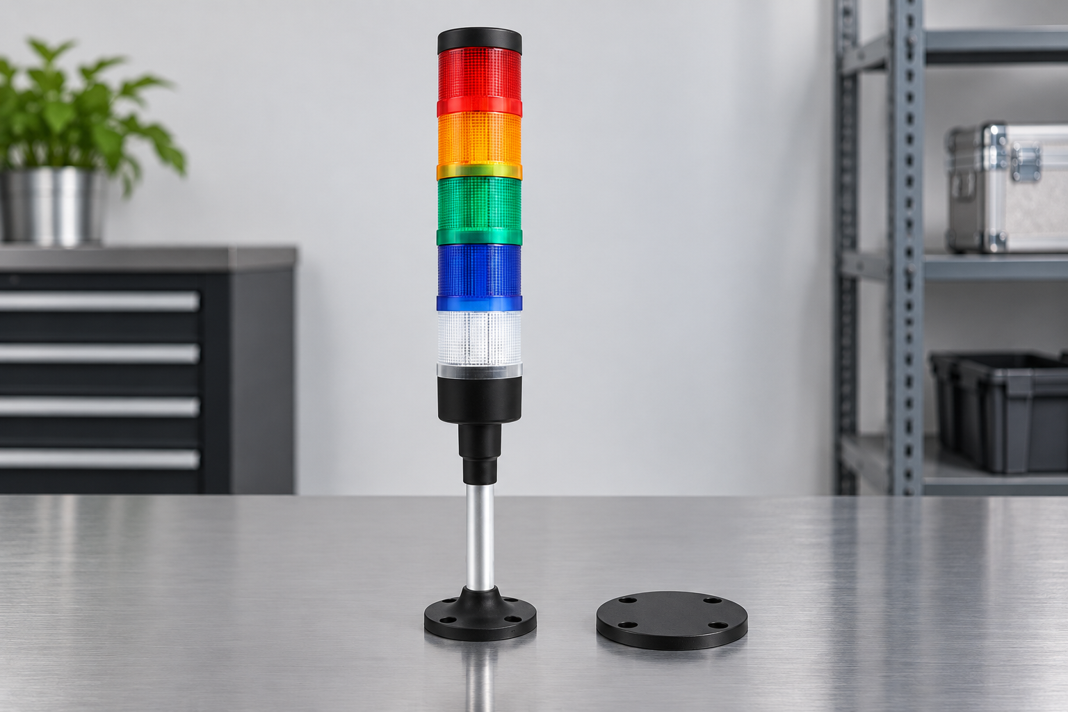
Start the drawing with the support surface
Identify the enclosure or frame material, thickness, finish and local geometry. A flat sheet, curved cover and structural frame present different mounting conditions. Check the area around the attachment, including nearby cutouts and unsupported edges. The responsible mechanical designer should establish whether reinforcement or a different support location is required.
Separate the base footprint from the cable hole. Confirm the fastener pattern, clearance and sealing arrangement from the approved drawing. Mark the intended orientation before drilling, particularly when the cable exit is offset or when service access is available from only one side. Remove burrs and machining debris without damaging the enclosure finish or internal equipment.
General fastening considerations, including joint geometry and loading, are discussed in the NASA Fastener Design Manual. Use it as engineering background. Its fastener examples do not supply allowable pole lengths, bolt torques or vibration ratings for this tower light assembly.
Review vibration and accidental contact
Machine vibration, door movement, cable pull and accidental knocks can load the tower differently from a static bench demonstration. Describe the intended operating conditions to the supplier and ask what evidence covers the complete light, pole and base arrangement. A product’s ability to illuminate correctly does not establish that its mounting arrangement is suitable for the machine’s motion.
Avoid using a hinged cover as a mounting surface without reviewing the repeated movement, cable routing and changing clearances. Consider what happens during maintenance when a door opens or a guard is removed. The light should not become an unintended handle or collide with nearby equipment. These checks belong in the machine layout review before fabrication.
For a tall or exposed assembly, the designer should determine whether representative mechanical testing is needed. Define the test configuration and acceptance criteria rather than claiming an unspecified vibration test proves suitability. Inspect retention, support damage and electrical continuity after the relevant qualification activities according to the approved plan.
Plan cable entry as part of the base selection
Determine whether the cable passes through the pole and base, exits beside the base or connects through a defined plug. Confirm that the chosen route protects the cable from sharp edges and moving parts. Provide the required strain relief and enough service allowance without leaving a loop where it can snag. Do not use the electrical conductors as mechanical support.
When a gland or connector forms part of an enclosure boundary, verify its compatibility with the cable and installation. A sealed light head does not automatically seal a newly drilled cabinet opening. Review the base gasket, fasteners, gland and surrounding surface together. Confirm which side of the assembly has a specified environmental rating and under what mounting conditions.
The HSE electrical safety introduction supports the general requirement for suitable equipment and competent electrical work. The HSE work equipment maintenance guidance also explains the need for arrangements that keep equipment safely maintained. Neither source certifies a particular base or cable-entry arrangement.
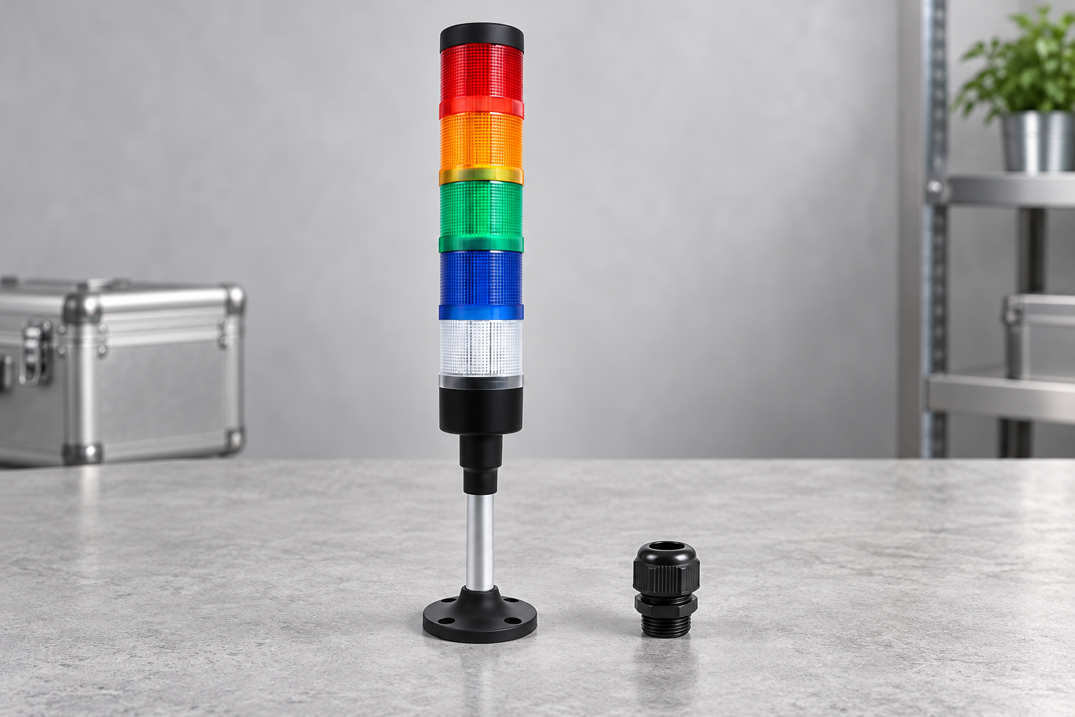
Use a mounting decision table
Use this qualitative table to prepare a supplier or design review. Add the actual drawing references and project acceptance requirements. No row establishes a universal load, torque, height or ingress-protection limit.
| Installation condition | Mounting question | Evidence to obtain |
|---|---|---|
| Compact enclosure with limited rear access | Can the direct base be installed and serviced? | Fastener access, cable exit and removal sequence |
| Light needs elevation above adjacent equipment | Is the proposed pole configuration approved? | Complete pole/base combination and support requirements |
| Attachment must be on a vertical frame | Is there a compatible bracket and orientation? | Bracket part number, drawing and attachment method |
| Machine or mounting door moves repeatedly | Are mechanical and cable conditions covered? | Movement review, clearances and appropriate qualification |
| Installation is exposed to cleaning or weather | How is the complete cable opening sealed? | Base/gasket/gland arrangement and exposure boundary |
| Replacement must use existing holes | Is the new base actually interchangeable? | Compared drawings, hardware and cable-route confirmation |
Keep visibility and mounting compatibility separate
After selecting a compatible attachment, confirm that the light can be seen from the intended operator positions. A mechanically sound base may still place the signal behind a guard, inside a visual obstruction or where a moving door hides it. Conversely, a visually convenient location may lack an adequate support surface. Resolve both requirements in the layout review.
Use the tower light placement guide for the visibility assessment. If a change in tier count alters the assembly, revisit the mechanical arrangement as well as the signal plan. The modular tower light tier guide helps define the signaling requirement before accessories are finalized.
Do not add elevation solely because a taller pole is available. Confirm that it solves a documented visibility problem and remains compatible with the mounting arrangement. Check sightlines with relevant doors and guards in their normal operating positions. Keep any assumptions about unusual access or temporary maintenance configurations explicit in the review.
Commission and maintain the installed assembly
Before electrical work, isolate the relevant equipment and follow the site’s safe working procedure. After mechanical installation, inspect the fasteners, support surface, cable protection, base seating and clearances. Confirm the light is stable under the approved inspection method. Avoid improvised pulling or twisting tests with undefined acceptance criteria.
Then verify each intended light and audible state using the machine’s commissioning plan. Check whether movement or cable routing causes intermittent operation. If a fault occurs, use the tower light troubleshooting guide to separate electrical symptoms from mechanical damage. A successful signal test should not close an unresolved support or sealing issue.
Include the base and cable entry in the maintenance record. Look for looseness, corrosion, damage, trapped cables and changes to surrounding equipment. The interval should follow the manufacturer’s guidance and the machine’s actual service conditions. Replace damaged or incompatible components through the approved process rather than repeatedly tightening an unknown assembly.
Send a complete request for quotation
Specify the tower code, tiers, audible function, proposed orientation, support material and thickness, cable route, service access and environment. Include the available mounting envelope and existing holes when replacing an installed light. Ask the supplier to identify every required accessory and provide the mounting drawing for that exact combination.
Request separate confirmation of mechanical compatibility and electrical compatibility. The correct base cannot establish the correct supply voltage or control circuit, and the correct voltage cannot establish a suitable mounting system. Keep the approved bill of materials and drawing revision with the machine documentation so future replacements preserve both interfaces.
Frequently asked questions
Are tower light bases universal?
No. Similar-looking lights can have different mounting patterns, pole connections, seals and cable routes. Use the manufacturer’s compatibility information for the exact light series and accessory configuration.
Can I put a longer pole on an existing base?
Only after confirming the complete proposed configuration is approved. A longer pole can change support loads, clearances and cable requirements. Do not assume the original installation evidence covers an improvised extension.
Does a waterproof light head seal the cabinet opening?
Not automatically. The base, gasket, fasteners and cable entry form additional interfaces. Confirm the complete installed boundary and its applicable environmental qualification before making a protection claim.
What must I compare when replacing a tower light base?
Compare the current and replacement drawings, fastener pattern, supplied hardware, support requirements, cable route and sealing arrangement. Also verify access and electrical compatibility before approving the replacement assembly.
Further learning
IIT Kharagpur lecture on fastener design. It supports understanding of mechanical joints; it does not supply an ONPOW nut torque, tower base load limit or an approved accessory combination.



