

Capacitive touch switch operation with gloves depends on the sensing design, glove material and thickness, panel construction, controller settings, and the user’s hand. A glove adds distance and material between the finger and electrode, which can reduce the change the sensor detects. Some engineered systems are designed and tested for particular gloves; that does not mean every capacitive switch will work with every glove. Validate the exact switch, glove, panel, and operating conditions before specifying it for production.
This guide gives a practical test method and selection checklist. ONPOW’s metal touch-switch product pages show the product form, but do not by themselves promise performance through a particular glove. Confirm model-specific behavior and installation instructions with the current documentation or ONPOW.
Why gloves change capacitive touch response
A capacitive sensor detects a change in the electrical field near its electrode. The operator’s finger contributes to that change. A glove separates the finger from the sensing surface and may change how strongly the field couples to the hand. Thin gloves, thick insulated gloves, dry gloves, and damp gloves can produce different results; material names alone do not predict performance.
Other parts of the assembly matter too. The electrode size, sensing controller, panel or cover, air gap, cable and ground reference influence the available signal. A system that works through a thin glove on a bench may fail through a thicker glove after installation in a grounded steel enclosure. The final machine, not a generic demonstration, is the relevant test environment.
Texas Instruments’ TIDA-00343 reference design describes a particular capacitive-touch HMI tested through a thick glass window and with gloves. Its result belongs to that design and its conditions. It is useful evidence that glove operation can be engineered, but not a guarantee for another product or for all glove types.
Build a glove validation matrix
| Test factor | Examples to include | Record for each test |
|---|---|---|
| Hand condition | Bare finger and each required glove | Detection consistency and missed touches |
| Glove construction | Thin disposable, coated fabric, insulated work glove | Brand/model, material, layers, and thickness if provided |
| Surface condition | Clean, dry; only other conditions approved for the product | Any false triggers, missed touches, or persistent active state |
| User variation | Multiple representative operators and hand sizes | Touch location, approach, and repeatability |
| Panel assembly | Production material, paint, overlay, gap, frame, mounting hardware | Configuration and revision used |
| Machine state | Startup, normal operation, switching loads, door open/closed where applicable | Unexpected events and controller/PLC states |
| Touch target | Center, edge, marked target, gloved fingertip or palm | Whether intended operating area is usable |
Use the table as a test plan, not a pass/fail specification. Define acceptance criteria with the machine builder and product supplier based on the operator task and risk assessment.
A practical glove test sequence
Begin with the exact product and current installation drawing. Record the part number, sensing controller, supply and output interface, panel material and thickness, mounting, cable route, ground/bond arrangement, and any configuration settings. Verify whether the product is intended to be touched directly or installed behind a separate cover. Do not add an overlay or alter the face without approval.
Test a known bare-finger baseline first. Use consistent approach and dwell times from a documented procedure, check the center and edge of the intended touch area, and record successful and missed detections. Then repeat the same sequence with each required glove. Include a range of representative users rather than relying on one person’s hand or one glove sample.
For every glove, repeat enough touches to identify inconsistent operation. Test whether the operator needs to press harder, hold longer, or touch a different area. A capacitive sensor has no mechanical travel unless the particular assembly adds it, so pushing harder may not solve the problem and could damage a surface or confuse the operator. If the switch provides a visible or audible acknowledgement, record both touch detection and the machine’s actual response; they are not necessarily the same event.
After the bench sequence, repeat the test with the production panel assembled and grounded. Close covers, fit gaskets, route cables, and energize adjacent equipment only through approved procedures. Test startup, normal switching conditions, and the required glove in the normal operating posture. If the interface controls machinery, conduct tests only in an approved safe state and verify the machine response separately from the sensor output.
Set acceptance criteria before the trial. Define the intended touch area, allowed response time, required repeatability, and acceptable no-touch events during an agreed observation period. These values come from the user task and machine requirements; they are not universal capacitive-switch limits. Record failed as well as successful trials and repeat the test after any change to the product, glove, panel material, cable, grounding, or controller setting.
Turn the validation into a purchase and change-control record
Keep the result tied to the exact combination that passed. Record the switch order code and revision, controller or firmware configuration where applicable, glove manufacturer and model, panel drawing revision, overlay material and thickness, air gap, coating, cable route, and grounding arrangement. Include the test method, users, number of attempts, missed detections, unintended activations, and the acceptance criteria agreed with the machine builder.
Ask the supplier to confirm in writing any glove-operation limit that is not stated in the published documentation. Attach the validated glove and panel configuration to the order or engineering approval so a substitute is not assumed equivalent. Re-test after a change to the glove, panel stack-up, controller settings, wiring, or switch model. A passed sample test is not evidence for an untested production variant.
When glove operation is unreliable
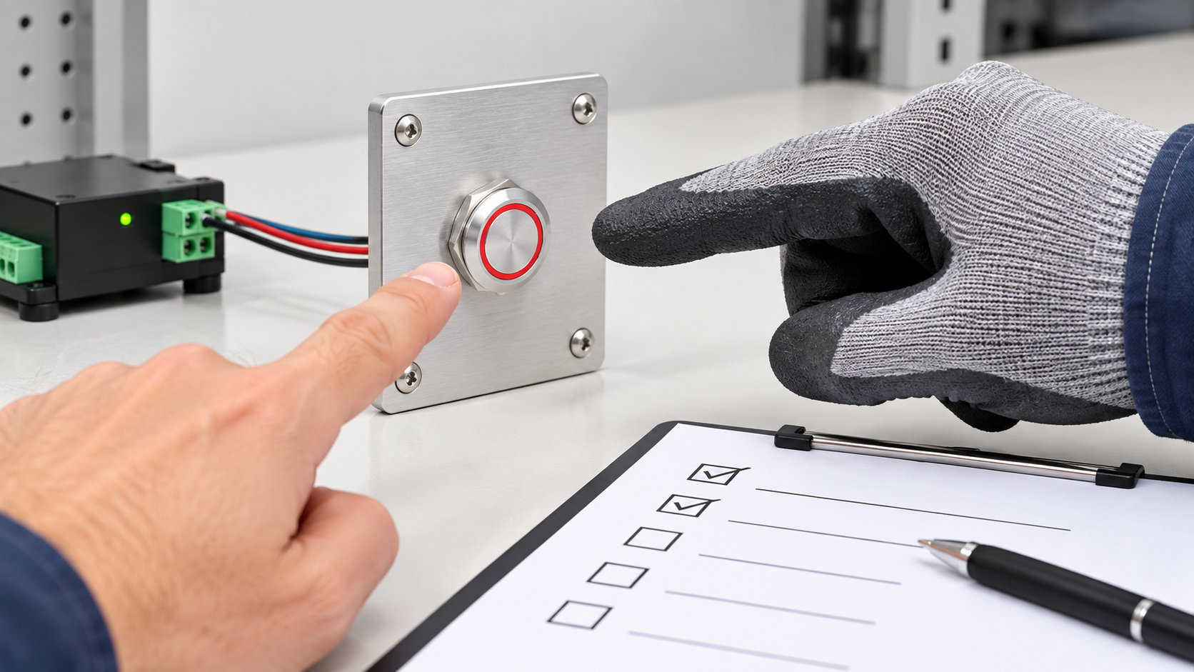
First confirm that the exact product is intended for glove operation and that the required glove is within any documented conditions. If documentation is silent, ask the supplier. Do not convert a successful test with one thin glove into a general claim for all gloves or all operators.
Next inspect variables that may have changed: glove type, moisture or residue if allowed, panel paint or coating, overlay thickness, panel bonding, cable routing, controller configuration, and nearby interference. Use the documented sensor tuning range. Do not increase sensitivity blindly, since the change may also increase false triggers or cause the system to remain active.
If the user needs reliable operation with thick insulated gloves, a different interface may be more appropriate. A mechanical push button provides tactile travel and a contact state, while a capacitive touch switch has a flat surface and electronic sensing behavior. A piezoelectric switch is another option with distinct mechanical and electrical characteristics. Compare the intended operator task, cleaning regime, panel environment, output requirements, and risk controls—not only the visual style. ONPOW’s touch switch versus push button guide و capacitive vs piezoelectric switch analysis provide additional selection context.
Do not confuse glove operation with environmental protection
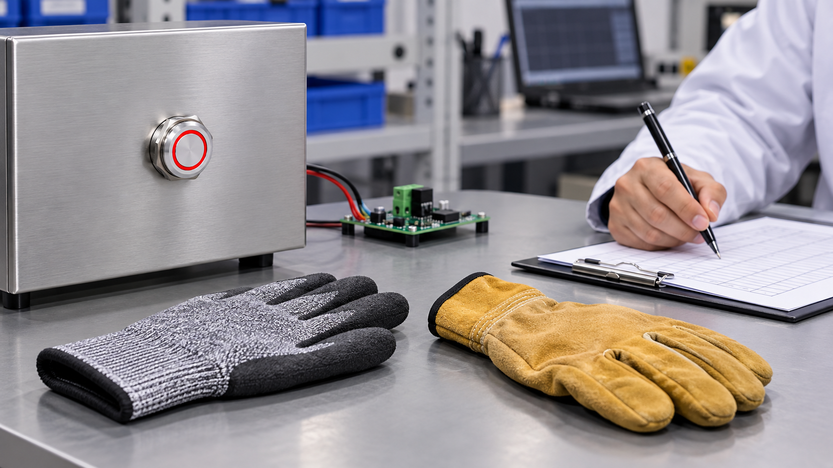
A glove-compatible touch design does not automatically establish water resistance, dust protection, outdoor suitability, or an ingress-protection rating. Those are separate product and assembly properties. Check the exact model rating, installation method, panel cutout, seal, and environmental test documentation. An indoor control panel may be cleaned or used in a harsh process area, but the test boundaries must come from the actual product specification.
Likewise, a visual indication that lights when a touch is sensed does not prove that a machine action has completed. If the operator needs confirmation, show the actual machine state separately. If the touch command affects a risk-sensitive function, validate the control architecture under applicable safety requirements; do not treat a general-purpose touch switch as a safety device without evidence.
الأسئلة الشائعة
Will any capacitive touch switch work with gloves?
No. Performance depends on the sensor design, glove, panel assembly, controller, and user. Test the specific glove and final installation or obtain documented confirmation for the exact configuration.
Are thick work gloves more difficult than thin gloves?
They may be, because additional material and distance can reduce the signal, but the outcome depends on the design and glove construction. Validate the actual glove rather than predicting from thickness alone.
Can I make a touch switch more sensitive for gloves?
Only if the product documentation provides an approved setting and the revised configuration is validated for both intended touches and no-touch stability. Do not adjust sensitivity by trial and error on production machinery.
Does glove-compatible mean waterproof or outdoor-rated?
No. Glove response and environmental protection are separate properties. Verify the exact ingress and environmental ratings for the model and assembled panel.
What should I record during a glove test?
Record the product and controller, glove identity, panel stack-up, grounding, settings, user, touch location, repeated detections, missed touches, false triggers, startup behavior, and the machine state during testing.
فيديو تعليمي
Microchip’s touch-solution demonstration shows a capacitive touch application designed for gloved operation. It is a vendor example with Korean narration and English subtitles; its behavior should not be treated as a specification for ONPOW products.
Watch Microchip’s gloved-touch solution demonstration.
المراجع
- Texas Instruments TIDA-00343: Low-Power Touch Through Glass Reference Design
- Texas Instruments CapTIvate design guide
- Microchip AN2934: Capacitive Touch Sensor Design Guide (PDF)
Related ONPOW products and guides
See the TS19A touch switch و TS22D touch switch pages for product-specific details. Read capacitive touch switch circuit basics for metal panels, capacitive touch sensitivity through glass and plastic, and the false-trigger troubleshooting guide for adjacent design considerations.



