

A limit switch symbol shows an electrical contact or a sensing function in the drawing’s stated reference condition. It does not, by itself, identify the installed switch’s terminal order, actuator setting, load rating, or safety suitability. Read the symbol together with its device tag, contact designation, mechanical-operation note, and wiring references. In a PLC ladder program, a contact-shaped instruction often tests a Boolean variable rather than depicting a physical contact. This guide explains that distinction with contact tables and an illustrative input example. Use the exact manufacturer diagram and the project’s approved drawing convention for the real installation.
Decide which kind of drawing you are reading
A machine can have an electrical schematic, a terminal drawing, a mechanical actuator drawing, and a controller program. Each answers a different question. The schematic shows circuit relationships. The terminal drawing tells the assembler where a conductor belongs. The actuator drawing locates the switch relative to moving parts. The program describes how the controller interprets its signals.
A contact symbol that appears in two of those documents can mean different things. In the electrical drawing, it can represent a physical contact pair. In a ladder program, a similar shape can represent a condition evaluated from an input bit or internal variable. Neither drawing should be used as a substitute for the other when identifying terminals or deciding how the machine responds.
Start by checking the drawing title, legend, revision, and cross-reference conventions. An old maintenance sketch may not use the same symbols as the current approved drawing. A software printout may also contain names that differ from the field-device tags. Resolve those differences before treating an apparent contact shape as a complete instruction.
Read NO and NC relative to the stated normal condition
Normally open and normally closed describe a contact relationship in a specified reference state. For many mechanically actuated limit devices, the reference is the unoperated actuator. COM to NO is open in that state, while COM to NC is closed for a typical changeover arrangement. Confirm that arrangement in the exact switch documentation rather than assuming it from the package.
The machine’s normal resting position may already operate the switch. A carriage parked at its end position can press the roller while the electrical drawing still uses the switch’s unoperated reference state. Record the physical machine position separately from the contact’s drawing condition. This avoids calling a perfectly consistent contact table incorrect simply because the actuator is pressed during inspection.
Some devices contain independent contacts, electronic outputs, or another mechanism. The device designation and manufacturer diagram determine what is actually present. A family name or a picture of a three-terminal case cannot establish that every ordered version has the same COM, NO, and NC map.
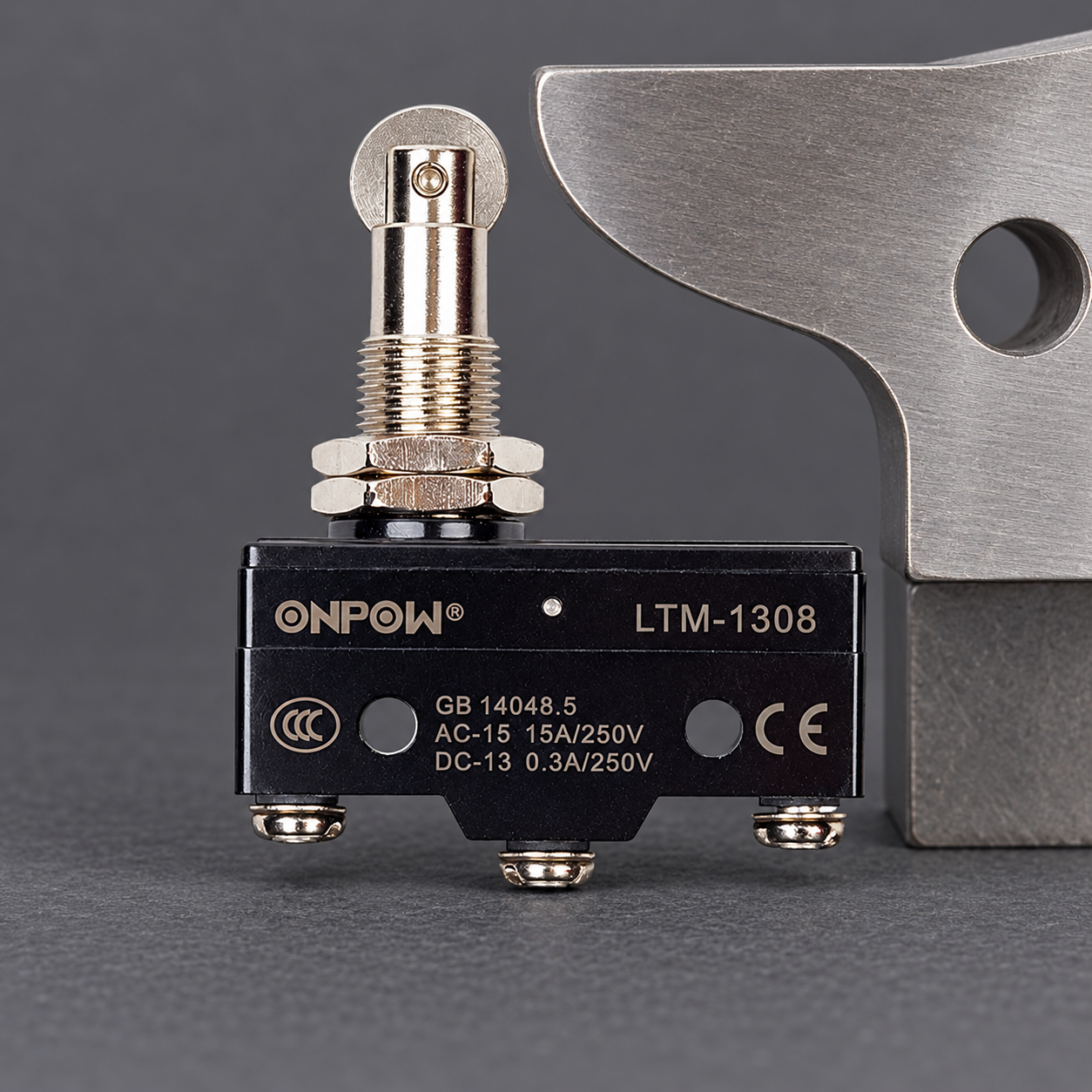
Use a contact table to translate the schematic into a requirement
The following table is an interpretation aid for a typical passive changeover arrangement. It is not the terminal map of the photographed LTM switch, a standardized symbol-number table, or a safety-circuit specification. Verify the exact model’s contact arrangement and normal state before applying it.
| Drawing information | Question it answers | What it does not establish |
|---|---|---|
| Normally open contact designation | Which path is open in the stated reference condition? | Universal terminal position or permitted switching current |
| Normally closed contact designation | Which path is closed in the stated reference condition? | Complete fault detection or a validated safety function |
| Common/changeover relationship | Which contact paths share the moving contact? | Controller input common, protective earth, or wire color |
| Mechanical-actuation indication | What operation changes the contact condition? | Installed operating point, overtravel, or machine stopping distance |
| Device tag and cross-reference | Where else is this device or contact documented? | Proof that the field device still matches the current drawing |
Treat a missing contact table as missing information. Do not choose a terminal simply because it is drawn on the left of the schematic or located in the center of the case. The supplier’s terminal-view direction is essential, especially where an underside view reverses the apparent layout.
For the electrical interface itself, read the limit switch wiring guide. This article focuses on interpreting drawings and software conditions, while that guide covers contact identification and circuit-interface review.
Where IEC symbol conventions fit
IEC 60617 is the international graphical-symbol resource for electrotechnical diagrams. The IEC’s TC 3 explanation of its symbol databases identifies IEC 60617 as the resource for diagram symbols. Use the applicable current symbol library and the project’s documentation rules for an approved drawing.
Do not confuse diagram symbols with the markings printed on equipment. A symbol library is also different from a manufacturer’s exact contact diagram. The latter identifies the ordered assembly’s terminals and relationships. A familiar standardized contact representation cannot fill in a missing product-specific contact table.
This guide does not reproduce a complete IEC library or assign an unverified IEC symbol reference number to a device. A drawing author must select the correct graphical representation and any qualifying information from the authorized library. A maintenance reader should check the drawing legend and device documentation rather than substituting a familiar internet icon.
A ladder contact tests a condition in the program
A PLC ladder editor may use an unnegated contact-shaped instruction to pass a true condition when its assigned variable is true, and a negated form when the assigned variable is false. The CODESYS documentation for an LD contact describes those Boolean operations. Other controllers use their own terminology and documentation.
That software operation does not choose whether a physical switch is wired through its NO or NC path. The program evaluates the variable value delivered by the configured input or internal logic. The circuit and input configuration determine how an operated switch produces that value.
Consider an illustrative signal named AtEnd. Suppose the documented circuit and controller configuration make AtEnd true when the carriage reaches the defined end position. The software can test AtEnd as a positive condition where end-position confirmation is required, and test its opposite elsewhere when permitted by the machine logic. Those decisions must follow the actual signal definition, not the superficial similarity between the instruction and a physical contact symbol.
Instructional ladder-contact sketches
The following plain-text sketches illustrate common ladder-editor contact notation. They are not IEC library reference drawings, device terminal maps, or a complete machine program. AtEnd is a hypothetical Boolean variable whose field meaning must be documented.
Positive test: --| |-- AtEnd
Negated test: --|/|-- AtEnd
With AtEnd true, the positive test passes the condition and the negated test does not. With AtEnd false, the negated test passes the condition and the positive test does not. Neither instruction tells an assembler which physical NO or NC terminals to wire.
Trace the field state, input value, and program condition separately
A useful commissioning record contains three columns: actual actuator condition, observed input value, and expected program interpretation. For a hypothetical NO feedback path with a documented input configuration, the unoperated device may give a false input and the operated device a true input. That example is not universal; another circuit can produce a different convention.
Write the signal meaning explicitly, such as carriage at validated end position, rather than relying on a variable called LimitNC to convey both the wiring and the machine condition. A name tied only to the contact type can become misleading after an approved interface change. Keep the electrical drawing and program names traceable through the device tag and input address.
Also define how unavailable or contradictory information is handled. A broken conductor can resemble a normal open path in some circuits, while a short can conceal a physical contact change. A basic input bit does not detect every fault. If feedback contributes to protection of people, the required hardware, diagnostics, architecture, and validation must come from the machine assessment.
A roller or plunger picture is not an electrical symbol
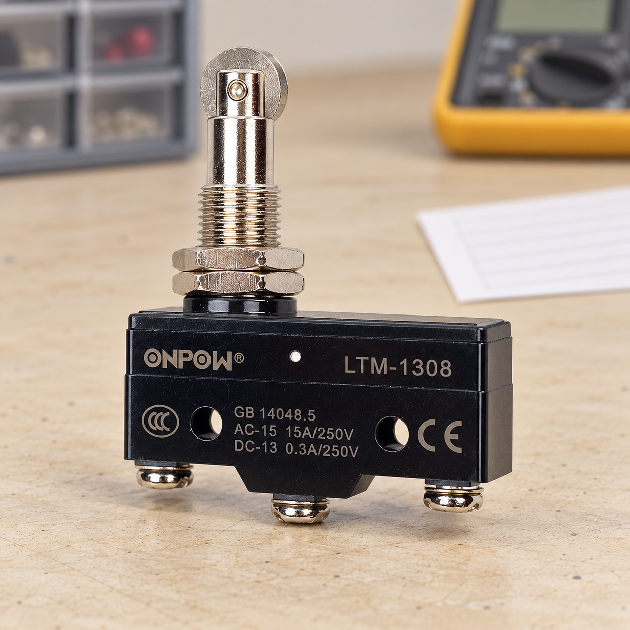
أونبو LTM-1308 product page shows a compact roller-plunger travel switch. Its photographs help identify the mechanical package, while the exact terminal and contact documentation establishes its electrical arrangement. The images here show a disconnected product, not an approved terminal map.
The actuator can change how motion reaches the contact mechanism without changing the meaning of the electrical contact designation. A roller, lever, or plunger must still be positioned and operated within its documented mechanical limits. Do not infer actuator direction, required travel, or an operating-force value from a schematic contact symbol.
ال limit switch actuator types guide explains mechanical selection, and the micro switch versus limit switch comparison addresses package and application differences. Those separate questions should remain visible in the engineering record rather than being compressed into one symbol.
Verify the drawing against the installed machine
Under the approved safe-work condition, confirm the full device order code, terminal identifiers, actuator position, and drawing revision. Qualified personnel must use the equipment’s required isolation and verification procedure before contact identification or changes. The official 29 CFR 1910.333 electrical work practices provide jurisdiction-specific context, not a machine-specific test procedure.
During authorized commissioning, verify the contact change, controller input, program interpretation, and final machine response as separate checkpoints. A correct input value does not prove that a stopping function has the required performance. Conversely, an incorrect screen label can mislead an operator even where the underlying electrical input changes correctly.
Record both approach and release behavior and the required handling of power interruption, cable faults, or conflicting states. Do not bridge a contact or bypass protection to make a symbol appear consistent with a presumed interpretation. Resolve the document, interface, or device discrepancy through the approved process.
For an inquiry, send the device tag, intended function, contact table, controller-input requirements, actuator drawing, and destination requirements. Ask ONPOW for the exact terminal and contact documentation for the ordered model before releasing the final drawing.
فيديو تعليمي
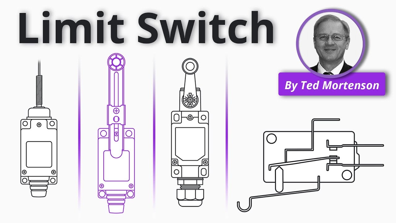
Limit Switch Explained | Working Principles by RealPars. General limit-switch operation; the exact device drawing establishes its terminal map, while the controller documentation establishes program semantics. Open the video on YouTube.
الأسئلة الشائعة
Does a limit switch symbol identify its terminal numbers?
No. It describes a contact or sensing function within the drawing convention. Terminal numbering and view direction come from the exact device documentation.
Does NC in a drawing mean the actuator is never pressed?
No. NC refers to the stated electrical reference condition. The installed machine’s resting position can already operate the actuator.
Is a negated ladder contact the same as a physical NC contact?
No. The ladder instruction tests a variable condition. The field circuit and input configuration determine the variable’s value.
Can a product photo replace a contact table?
No. A photo shows the package and visible terminals but cannot establish every internal contact relationship or permitted operating condition.
What should be checked when a drawing and the machine disagree?
Confirm the order code, diagram revision, terminal view, actuator condition, controller input definition, and expected machine response under the approved procedure.



