

رمز مفتاح الحد يظهر اتصالًا كهربائيًا أو وظيفة استشعار في الحالة المرجعية المحددة للرسم. لا يحدد، بمفرده، ترتيب أطراف المفتاح المثبت، إعداد المشغل، تصنيف الحمل، أو ملاءمته للسلامة. اقرأ الرمز مع علامة جهازه، تسمية الاتصال، ملاحظة التشغيل الميكانيكي، ومراجع التوصيل. في برنامج سلم PLC، غالبًا ما تختبر تعليمات على شكل اتصال متغير بولياني بدلاً من تصوير اتصال مادي. يوضح هذا الدليل هذا التمييز باستخدام جداول الاتصالات ومثال إدخال توضيحي. استخدم الرسم البياني الدقيق للشركة المصنعة واتفاقية الرسم المعتمدة للمشروع للتثبيت الحقيقي.
حدد نوع الرسم الذي تقرأه
يمكن أن تحتوي الآلة على مخطط كهربائي، رسم طرفي، رسم مشغل ميكانيكي، وبرنامج وحدة تحكم. كل واحد يجيب على سؤال مختلف. يُظهر المخطط علاقات الدائرة. يخبر رسم الطرفية عن مكان انتماء الموصل. يحدد رسم المشغل موقع المفتاح بالنسبة للأجزاء المتحركة. يصف البرنامج كيف يفسر وحدة التحكم إشاراتها.
رمز الاتصال الذي يظهر في اثنين من تلك الوثائق يمكن أن يعني أشياء مختلفة. في الرسم الكهربائي، يمكن أن يمثل زوج اتصال مادي. في برنامج سلم، يمكن أن يمثل شكل مماثل حالة مُقيمة من بت إدخال أو متغير داخلي. لا ينبغي استخدام أي من الرسمين كبديل للآخر عند تحديد الأطراف أو قرار كيفية استجابة الآلة.
ابدأ بفحص عنوان الرسم، الأسطورة، المراجعة، واتفاقيات المراجع المتقاطعة. قد لا يستخدم رسم الصيانة القديم نفس الرموز مثل الرسم المعتمد الحالي. قد يحتوي طباعة البرنامج أيضًا على أسماء تختلف عن علامات الأجهزة الميدانية. حل تلك الاختلافات قبل اعتبار شكل الاتصال الظاهر كتعليمات كاملة.
اقرأ NO و NC بالنسبة للحالة الطبيعية المحددة
الوضع الطبيعي المفتوح والمغلق طبيعيًا يصفان علاقة اتصال في حالة مرجعية محددة. بالنسبة للعديد من أجهزة الحد الميكانيكية، الحالة المرجعية هي المشغل غير المشغل. يكون COM إلى NO مفتوحًا في تلك الحالة، بينما يكون COM إلى NC مغلقًا لترتيب التبديل النموذجي. أكد ذلك الترتيب في وثائق المفتاح الدقيقة بدلاً من افتراضه من العبوة.
قد يكون وضع الراحة الطبيعي للآلة قد يشغل المفتاح بالفعل. يمكن أن يضغط عربة متوقفة عند وضعها النهائي على البكرة بينما لا تزال الرسمة الكهربائية تستخدم الحالة المرجعية غير المشغلة للمفتاح. سجل وضع الآلة المادي بشكل منفصل عن حالة الاتصال في الرسم. هذا يتجنب اعتبار جدول الاتصال المتطابق تمامًا غير صحيح لمجرد أن المشغل مضغوط أثناء الفحص.
بعض الأجهزة تحتوي على اتصالات مستقلة، مخرجات إلكترونية، أو آلية أخرى. يحدد تسمية الجهاز ورسم الشركة المصنعة ما هو موجود فعليًا. لا يمكن لاسم العائلة أو صورة لحالة ذات ثلاثة أطراف أن يثبت أن كل إصدار مطلوب لديه نفس خريطة COM و NO و NC.
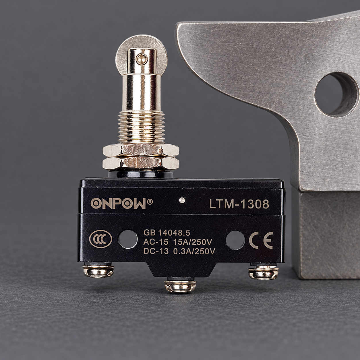
استخدم جدول اتصال لترجمة المخطط إلى متطلب
الجدول التالي هو وسيلة تفسير لترتيب تبديل سلبي نموذجي. إنه ليس خريطة أطراف مفتاح LTM المصور، جدول رموز موحد، أو مواصفة دائرة أمان. تحقق من ترتيب الاتصال والحالة الطبيعية للطراز الدقيق قبل تطبيقه.
| معلومات الرسم | السؤال الذي يجيب عليه | ما الذي لا يثبته |
|---|---|---|
| تعيين التلامس المفتوح عادةً | أي مسار مفتوح في حالة المرجع المذكورة؟ | وضع الطرفية العامة أو التيار المسموح بالتبديل |
| تعيين التلامس المغلق عادةً | أي مسار مغلق في حالة المرجع المذكورة؟ | كشف كامل عن العطل أو وظيفة أمان معتمدة |
| العلاقة المشتركة/التبديل | أي مسارات التلامس تشترك في التلامس المتحرك؟ | مشترك إدخال وحدة التحكم، الأرض الوقائية، أو لون السلك |
| مؤشر التشغيل الميكانيكي | أي عملية تغير حالة التلامس؟ | نقطة التشغيل المثبتة، تجاوز الحركة، أو مسافة إيقاف الآلة |
| علامة الجهاز والمرجع المتقاطع | أين تم توثيق هذا الجهاز أو التلامس أيضًا؟ | إثبات أن جهاز الحقل لا يزال يتطابق مع الرسم الحالي |
معاملة جدول التلامس المفقود كمعلومات مفقودة. لا تختار طرفية لمجرد أنها مرسومة على يسار المخطط أو تقع في وسط الحالة. اتجاه عرض الطرفية من قبل المورد ضروري، خاصة حيث يعكس عرض الجانب السفلي التخطيط الظاهر.
بالنسبة للواجهة الكهربائية نفسها، اقرأ دليل توصيل مفتاح الحد. يركز هذا المقال على تفسير الرسومات وظروف البرمجيات، بينما يغطي ذلك الدليل تحديد التلامس ومراجعة دائرة الاتصال.
حيث تتناسب اتفاقيات رموز IEC
IEC 60617 is the international graphical-symbol resource for electrotechnical diagrams. The IEC’s TC 3 explanation of its symbol databases identifies IEC 60617 as the resource for diagram symbols. Use the applicable current symbol library and the project’s documentation rules for an approved drawing.
Do not confuse diagram symbols with the markings printed on equipment. A symbol library is also different from a manufacturer’s exact contact diagram. The latter identifies the ordered assembly’s terminals and relationships. A familiar standardized contact representation cannot fill in a missing product-specific contact table.
This guide does not reproduce a complete IEC library or assign an unverified IEC symbol reference number to a device. A drawing author must select the correct graphical representation and any qualifying information from the authorized library. A maintenance reader should check the drawing legend and device documentation rather than substituting a familiar internet icon.
يختبر اتصال السلم حالة في البرنامج
A PLC ladder editor may use an unnegated contact-shaped instruction to pass a true condition when its assigned variable is true, and a negated form when the assigned variable is false. The CODESYS documentation for an LD contact describes those Boolean operations. Other controllers use their own terminology and documentation.
That software operation does not choose whether a physical switch is wired through its NO or NC path. The program evaluates the variable value delivered by the configured input or internal logic. The circuit and input configuration determine how an operated switch produces that value.
Consider an illustrative signal named AtEnd. Suppose the documented circuit and controller configuration make AtEnd true when the carriage reaches the defined end position. The software can test AtEnd as a positive condition where end-position confirmation is required, and test its opposite elsewhere when permitted by the machine logic. Those decisions must follow the actual signal definition, not the superficial similarity between the instruction and a physical contact symbol.
Instructional ladder-contact sketches
The following plain-text sketches illustrate common ladder-editor contact notation. They are not IEC library reference drawings, device terminal maps, or a complete machine program. AtEnd is a hypothetical Boolean variable whose field meaning must be documented.
Positive test: --| |-- AtEnd
Negated test: --|/|-- AtEnd
With AtEnd true, the positive test passes the condition and the negated test does not. With AtEnd false, the negated test passes the condition and the positive test does not. Neither instruction tells an assembler which physical NO or NC terminals to wire.
تتبع حالة الحقل، قيمة الإدخال، وحالة البرنامج بشكل منفصل
A useful commissioning record contains three columns: actual actuator condition, observed input value, and expected program interpretation. For a hypothetical NO feedback path with a documented input configuration, the unoperated device may give a false input and the operated device a true input. That example is not universal; another circuit can produce a different convention.
Write the signal meaning explicitly, such as carriage at validated end position, rather than relying on a variable called LimitNC to convey both the wiring and the machine condition. A name tied only to the contact type can become misleading after an approved interface change. Keep the electrical drawing and program names traceable through the device tag and input address.
Also define how unavailable or contradictory information is handled. A broken conductor can resemble a normal open path in some circuits, while a short can conceal a physical contact change. A basic input bit does not detect every fault. If feedback contributes to protection of people, the required hardware, diagnostics, architecture, and validation must come from the machine assessment.
صورة بكرة أو مكبس ليست رمزًا كهربائيًا
أونبو LTM-1308 product page shows a compact roller-plunger travel switch. Its photographs help identify the mechanical package, while the exact terminal and contact documentation establishes its electrical arrangement. The images here show a disconnected product, not an approved terminal map.
The actuator can change how motion reaches the contact mechanism without changing the meaning of the electrical contact designation. A roller, lever, or plunger must still be positioned and operated within its documented mechanical limits. Do not infer actuator direction, required travel, or an operating-force value from a schematic contact symbol.
ال limit switch actuator types guide explains mechanical selection, and the micro switch versus limit switch comparison addresses package and application differences. Those separate questions should remain visible in the engineering record rather than being compressed into one symbol.
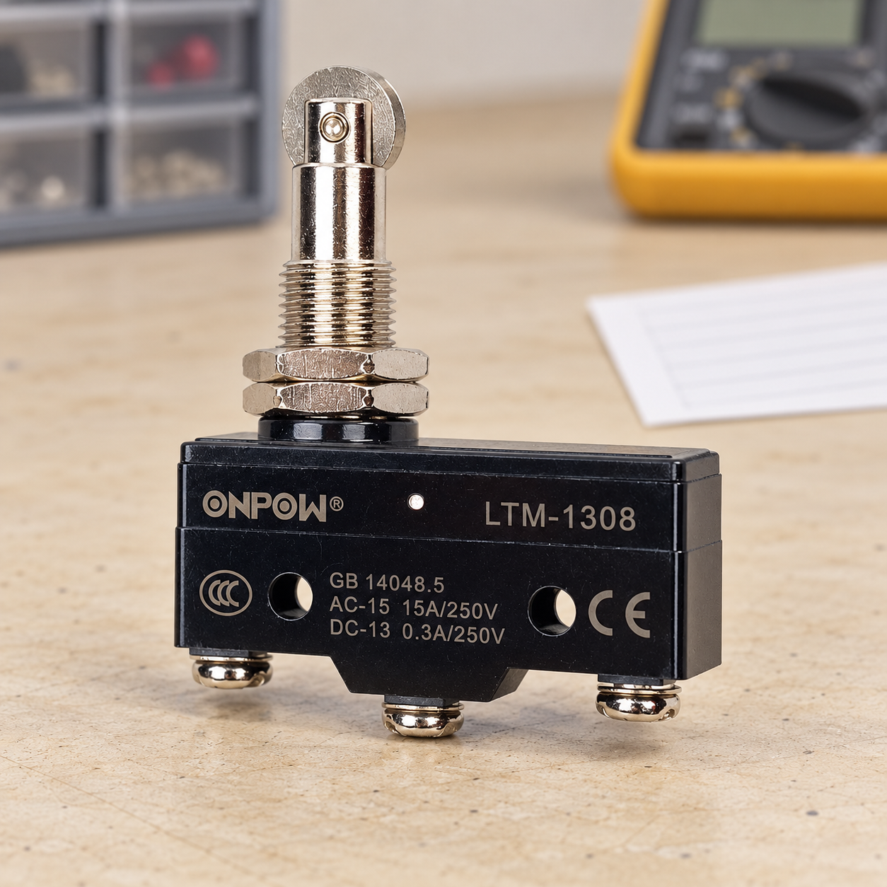
تحقق من الرسم مقابل الآلة المثبتة
Under the approved safe-work condition, confirm the full device order code, terminal identifiers, actuator position, and drawing revision. Qualified personnel must use the equipment’s required isolation and verification procedure before contact identification or changes. The official ممارسات العمل الكهربائية 29 CFR 1910.333 provide jurisdiction-specific context, not a machine-specific test procedure.
During authorized commissioning, verify the contact change, controller input, program interpretation, and final machine response as separate checkpoints. A correct input value does not prove that a stopping function has the required performance. Conversely, an incorrect screen label can mislead an operator even where the underlying electrical input changes correctly.
Record both approach and release behavior and the required handling of power interruption, cable faults, or conflicting states. Do not bridge a contact or bypass protection to make a symbol appear consistent with a presumed interpretation. Resolve the document, interface, or device discrepancy through the approved process.
For an inquiry, send the device tag, intended function, contact table, controller-input requirements, actuator drawing, and destination requirements. Ask ONPOW for the exact terminal and contact documentation for the ordered model before releasing the final drawing.
فيديو تعليمي
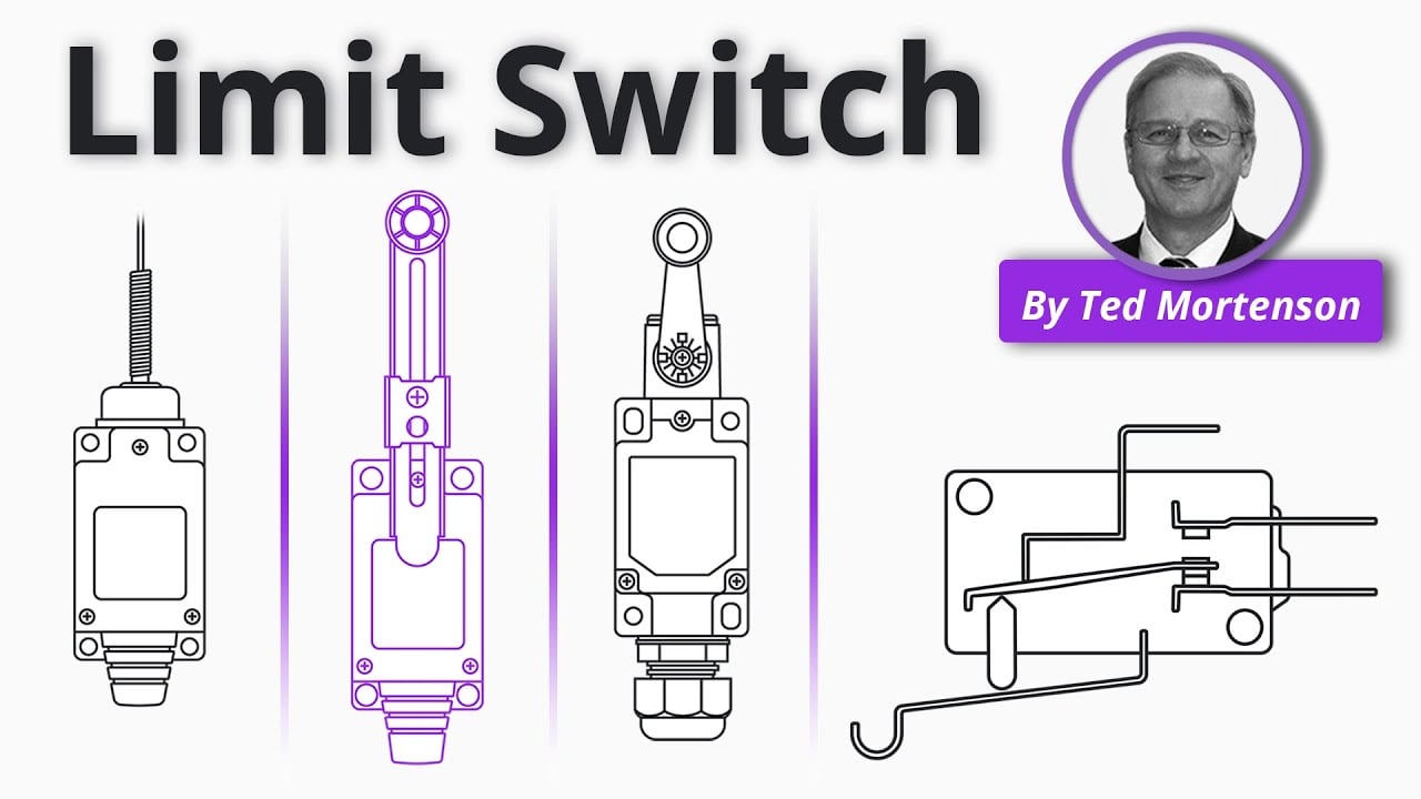
Limit Switch Explained | Working Principles by RealPars. General limit-switch operation; the exact device drawing establishes its terminal map, while the controller documentation establishes program semantics. افتح الفيديو على YouTube.
الأسئلة الشائعة
هل يحدد رمز مفتاح نهاية المشوار أرقام أطراف التوصيل الخاصة به؟
No. It describes a contact or sensing function within the drawing convention. Terminal numbering and view direction come from the exact device documentation.
هل يعني الرمز NC في الرسم أن المشغّل لا يتم الضغط عليه مطلقًا؟
لا. يشير NC إلى الحالة الكهربائية المرجعية المذكورة. يمكن لوضع الراحة للآلة المثبتة أن تشغل المشغل بالفعل.
هل الاتصال السلبي للسلم هو نفسه الاتصال المادي NC؟
لا. اختبار تعليمات السلم يختبر حالة متغيرة. دائرة الحقل وتكوين الإدخال يحددان قيمة المتغير.
Can a product photo replace a contact table?
لا. تظهر الصورة العبوة والأطراف المرئية ولكن لا يمكنها إقامة كل علاقة اتصال داخلية أو ظروف تشغيل مسموح بها.
ماذا يجب التحقق منه عندما يختلف الرسم والآلة؟
Confirm the order code, diagram revision, terminal view, actuator condition, controller input definition, and expected machine response under the approved procedure.



