

Steady, flashing and rotating warning lights describe different ways a visual signal changes over time. A steady light remains illuminated while commanded. A flashing light alternates illumination according to a defined pattern. A rotating beacon produces a moving apparent signal through its documented optical or mechanical design. Select the mode from the message, viewing positions, surrounding signals and operator response. Do not infer the available modes from the lens shape or tower colors alone. A tower light’s number of tiers describes its physical signal arrangement, while steady, flashing and rotating describe behavior that must be confirmed for the exact supplied version.
Separate physical format from signal behavior
A tower light stacks several visible sections above one another. A beacon can use another housing format. A panel indicator is normally placed in a local control surface. Each format has different placement and viewing characteristics, but none of those formats alone establishes its temporal behavior.
A catalogue photograph shows the housing and lens colors. It does not demonstrate the control arrangement, flash sequence, rotation method, or how simultaneous commands are handled. Obtain those details from the exact product documentation and the responsible control design.
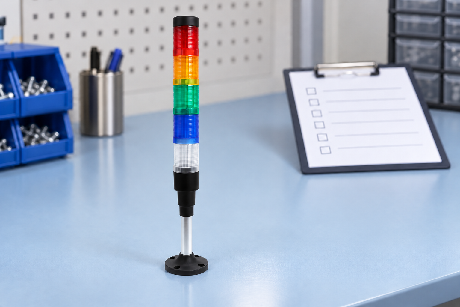
For a real product reference, review the ONPOW multi-tier warning light. The product illustration in this article preserves its visible five-tier arrangement. It is an identification illustration, not evidence that the pictured unit has a rotating mode or any unconfirmed internal timing function.
What a steady light communicates
A steady indication can present a continuing equipment state. The meaning depends on the machine’s documented conventions, labels and operating instructions. Avoid treating one color as a complete universal message without checking the actual equipment requirements.
A steady signal can be useful when the operator needs to see a status repeatedly without waiting for an illuminated portion of a cycle. It may also provide a continuing indication after another alarm channel has been acknowledged. These are control-design choices, not features guaranteed by every steady-light product.
Consider whether the light will stand out among other continuously illuminated equipment. A steady signal that looks identical to a normal nearby status light may be visible yet ambiguous. Improve the documented message and placement rather than assuming that any illuminated section will attract the intended attention.
What flashing adds to the message
Flashing creates a changing visual signal. It can help distinguish a condition from a steady status in some environments. The effectiveness depends on timing, contrast, viewing positions and other signals; “flashing” alone does not guarantee recognition.
Define who generates the pattern. Some supplied versions contain internal flashing behavior, while other arrangements require an external controller command. Ask for the exact input and timing responsibility. Do not assume that cycling the supply to any lamp is a permitted or suitable way to obtain the desired flash pattern.
Record how flashing begins, ends and behaves after interrupted power. If the machine uses several flashing sections or several nearby towers, review their combined appearance. Multiple uncoordinated signals can make it difficult to identify the alarm source or priority.

Understand the claimed rotation method
“Rotating” can describe a documented mechanical rotating mechanism or an apparent moving-light effect produced by a particular optical/electronic design. Obtain the offered product’s description instead of inferring moving internal parts from a sales term.
That distinction affects maintenance expectations and application review. A device with a moving mechanism has different relevant parts from a device producing a moving visual effect without that mechanism. Do not assign service intervals, lifetime or replacement procedures without actual manufacturer information.
A rotating beacon also should not be assumed to deliver an identical signal in every direction or mounting condition. Check the documented viewing characteristics and verify the required positions in the actual installation. Machinery, structures and adjacent lights can obstruct or confuse the result.
A mode-comparison decision table
| Mode | Useful selection question | Information to confirm | Installed observation |
|---|---|---|---|
| Steady | Does the operator need a continuously visible state? | Input arrangement, state meaning and color selection | State remains distinguishable among normal nearby lights |
| وميض | Must the signal distinguish attention from continuing status? | Internal or external timing, sequence and restart behavior | Full pattern is recognizable from required viewing points |
| Rotating or apparent rotating | Does the application require a moving visual effect? | Actual mechanism, optical behavior and maintenance information | Signal is recognizable in the complete mounting arrangement |
| Several tower tiers | Do separate conditions need separate visual identification? | Tier configuration, control inputs and simultaneous-command behavior | Operators can identify the source and intended message |
| Combined light and sound | Must people notice the condition while facing elsewhere? | Relationship between audible and visual outputs | Both channels communicate compatible actions |
This comparison does not declare one mode universally superior. The acceptance criterion is the required equipment message and response under representative conditions.
Choose a mode from the operator’s task
Identify whether the light communicates normal status, an action request, a continuing fault, or another defined condition. Establish the audience and required response. An unfamiliar flashing pattern cannot substitute for a clear procedure.
Review the operator’s normal attention direction and task. Someone facing a local control panel has a different view from a worker moving through an aisle. A tower above the machine may help locate the source, while a panel indicator can provide more local context.
ال tower light versus panel indicator guide addresses that format choice. The tower-light placement guide addresses location and visibility. This article focuses on temporal modes so these related decisions can be considered together without confusing them.
Keep color, timing and priority consistent
Use the equipment’s documented signal conventions and applicable requirements. A change from steady to flashing can change how a worker interprets a condition even when the color remains the same. Review that change as a message change, not simply an appearance improvement.
Define what happens when several conditions exist at once. Can several tiers be illuminated together? Does the controller apply a priority or a sequence? Does acknowledgement change the mode? The required behavior belongs in the control design and operator instructions.
Do not assume that an internal flashing option provides configurable priority logic. Nor should a product’s available colors be treated as a complete alarm hierarchy. Confirm actual device behavior and define the system message separately.
For U.S. workplaces where the installation is part of an employee alarm system, 29 CFR 1910.165 provides relevant system requirements. Confirm the scope for the actual application; a machine status tower is not automatically a complete workplace alarm system.
Confirm the electrical interface and mounting
Check the supplied version’s documented voltage, input arrangement and connection diagram. A shared common connection and separate signal inputs can be important to control compatibility, but the actual arrangement must come from the exact documentation. Use the complementary tower-light wiring guide for the questions to resolve.
For externally commanded flashing, establish the output hardware and control timing. A relay output and a semiconductor output have different relevant characteristics. Do not assign a generic switching rate or assume every controller output is suitable for a repeatedly operated signal load.
Keep mounting, cable entries, environmental exposure and access for maintenance within the documented installation. A sealing rating alone does not establish sunlight resistance, chemical compatibility or suitability outdoors. If changing the mounting position improves visibility, review the complete installation rather than compromising protection or access.
Verify recognition across the required area
Test in the lighting and equipment conditions that represent normal use. Daylight, overhead lighting, reflections, obstructions and adjacent signals can change recognition. A photograph taken in a dark room is not proof that the signal works in the production area.
Observe the entire sequence. For a flashing or moving effect, give the observer enough time to identify the pattern and source. Verify that an arriving worker can understand the message rather than relying on someone who already knows which signal is being tested.
Where a signal includes a buzzer, verify the acoustic channel separately. Light visibility does not establish sound recognition, and sound does not establish visibility. The industrial buzzer frequency guide explains a complementary acoustic selection issue.
Servicing and electrical inspection should follow the equipment’s approved procedures. For U.S. electrical work, 29 CFR 1910.333 provides relevant work-practice requirements. A successful visual demonstration does not replace the required inspection or return-to-service process.
Record the accepted mode and replacement information
Retain the order code, physical tier arrangement, color selections, input diagram, internal/external timing responsibility, acknowledgement behavior and restored-power behavior. Include the mounting location and the tested viewing positions.
When replacing a device, compare its behavior as well as its physical fit. A replacement that lights continuously where the original flashed can change the equipment message. A different apparent rotation or startup sequence may also require review.
If the installation changes, review the earlier visibility evidence. Moving a machine, adding guarding or changing adjacent lighting can make a previously acceptable signal harder to recognize. Keep those conditions explicit in the acceptance record so later maintenance can assess whether the evidence still applies.
The accompanying neutral educational video discusses engineering safety and the role of understandable warnings. It supports the need for a coherent signal system; it does not prescribe a mode, color code or acceptance limit for the pictured ONPOW device.

الأسئلة الشائعة
Does a tower light automatically provide flashing operation?
No. Confirm the exact supplied version and whether timing is internal or must be generated by the controller. A tower format alone does not establish available modes.
Does rotating always mean a motor-driven reflector?
No universal assumption is appropriate. Ask whether the offered device has a mechanical rotating mechanism or an apparent moving-light effect, and obtain its actual documentation.
Is flashing always better than steady indication?
No. Select the mode from the message, operator task, surrounding signals and required response. Verify recognition under representative installed conditions.
Can I change the mode without reviewing the alarm meaning?
A timing change can alter how operators interpret the signal. Review the documented message, acknowledgement and priority behavior before accepting the change.
What needs checking when a warning light is replaced?
Confirm order code, physical configuration, electrical interface, mode, timing, restart behavior, mounting and visibility from the required positions.



