

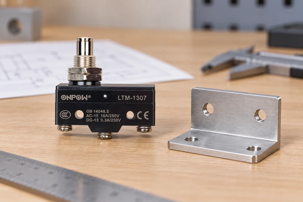
A pin plunger micro switch is actuated by motion along its plunger axis. Choose it when the target can provide a controlled, substantially axial push with enough travel to operate and release the contact, without using the switch as a mechanical stop. The key selection checks are alignment, operating position, permissible overtravel, operating force, mounting stiffness, and target return clearance. A pin plunger can provide a compact interface, but it tolerates a different motion path from a roller or lever actuator. Verify the exact model’s drawing and travel data before setting the bracket or machining the cam.
Start with the target’s actual motion
Sketch where the target first meets the plunger, how far it continues after contact change, and where it leaves during return. Include the direction of motion. A target moving straight toward the plunger presents a different mechanical problem from a sliding target brushing across the end. The latter can introduce lateral loading and friction.
Measure the mechanism at its practical extremes, not only its nominal drawing position. Manufacturing tolerance, bracket adjustment, bearing clearance, thermal expansion, and wear can change the contact path. A switch that works on a carefully aligned prototype may bind after the production assembly shifts a small amount.
If the application has substantial sliding contact or an angled approach, consider whether a roller, lever, or another actuator is more appropriate. Read the related micro switch roller and cam guide for those alternatives. Avoid reshaping the target to suit a pin plunger until the complete movement has been reviewed.
Separate operating travel from the end of allowed movement
The contact changes at the specified operating point. The target can usually continue through a permitted amount of overtravel, but that permitted movement is not unlimited. A mechanical end position inside the switch is not a production-machine stop. External stops should control the target so the switch remains within its approved range.
The actuator also needs to return far enough to release the contact. Operating and release positions may differ because of the snap mechanism. Leave enough return clearance after the target moves away; a target that stops just short of the release point can keep the signal operated.
| حالة التركيب | ما الذي يجب التحقق منه | Typical consequence if overlooked |
|---|---|---|
| First target contact | Target approaches the intended plunger surface | Edge contact or side force |
| Contact operation | Worst-case travel crosses the specified operating point | Missed position signal |
| Continued target movement | Remaining travel stays within the permitted range | Internal damage or bracket loading |
| Target withdrawal | Plunger can pass the release position and return | Signal fails to reset |
| Machine stop | Independent structure limits the target movement | Switch becomes an unintended stop |
| Cable routing | Wiring does not pull on the switch or bracket | Position changes or terminal damage |
These checks describe a design method. They do not supply universal travel dimensions. Use the selected actuator’s data and its defined measurement reference.
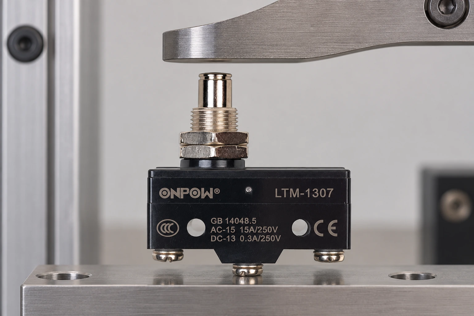
Plan an axial load path and a stable contact surface
A plunger should receive the direction of force allowed by its manufacturer. When the target contacts an edge or rubs sideways, the resulting moment can increase friction and reduce reliable return. A larger target pad does not solve an incorrect force direction by itself; the pad must still be aligned to the allowed motion.
Keep the target contact surface consistent over the operating stroke. Surface roughness, a burr, or a sharp edge can change friction and wear. The application may require a rounded contact surface or a properly designed cam, but the shape must be selected from the model’s mounting and actuator guidance.
Check whether the target can overrun, deflect, or strike the plunger during a fault. If an unintended impact is possible, the mechanical design needs to address it. Do not rely on the normal operating-force value as an impact rating. Force during a collision can be much higher than force during slow controlled operation.
Mounting stiffness controls repeatability
cURL Too many subrequests by single Worker invocation. To configure this limit, refer to https://developers.cloudflare.com/workers/wrangler/configuration/#limits.
cURL Too many subrequests by single Worker invocation. To configure this limit, refer to https://developers.cloudflare.com/workers/wrangler/configuration/#limits.
ال cURL Too many subrequests by single Worker invocation. To configure this limit, refer to https://developers.cloudflare.com/workers/wrangler/configuration/#limits cURL Too many subrequests by single Worker invocation. To configure this limit, refer to https://developers.cloudflare.com/workers/wrangler/configuration/#limits.
Build a tolerance budget before final adjustment
cURL Too many subrequests by single Worker invocation. To configure this limit, refer to https://developers.cloudflare.com/workers/wrangler/configuration/#limits.
cURL Too many subrequests by single Worker invocation. To configure this limit, refer to https://developers.cloudflare.com/workers/wrangler/configuration/#limits.
cURL Too many subrequests by single Worker invocation. To configure this limit, refer to https://developers.cloudflare.com/workers/wrangler/configuration/#limits.
Match force to the mechanism, not only the component
cURL Too many subrequests by single Worker invocation. To configure this limit, refer to https://developers.cloudflare.com/workers/wrangler/configuration/#limits.
cURL Too many subrequests by single Worker invocation. To configure this limit, refer to https://developers.cloudflare.com/workers/wrangler/configuration/#limits.
For the wider procurement questions, use the قائمة فحص اختيار المفتاح الصغير الصناعي. The standards context in IEC 60947-5-1 does not replace the component’s declared ratings or test evidence.
Check the electrical signal after the mechanical fit
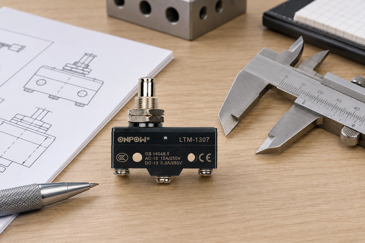
The contact arrangement and the actuator shape are separate specification choices. A pin plunger does not identify COM, NO, or NC, and it does not establish the load rating. Confirm the contact diagram and receiving-input requirements for the selected variant. Record the normal mechanical state and what the controller should indicate at that position.
A mounting issue can look like an electrical problem. If the contact changes when the plunger is operated by hand but not when the machine target passes, compare the target’s motion with the specified operating point. If the signal fails to reset, check return clearance and binding before changing the controller’s logic.
ال دليل مبدأ عمل المفتاح الدقيق explains the snap mechanism, while the دليل الميكرو مفتاح مقابل مفتاح الحد helps separate component selection from complete packaged position sensing.
Inspect and commission without improvised live adjustment
Installed machinery must be inspected under its approved energy-control and electrical-work procedures. Qualified personnel should account for unexpected movement and stored energy. In United States workplaces, consult the applicable requirements in 29 CFR 1910.147 و المادة 29 CFR 1910.333. Pressing a control stop is not equivalent to isolating energy.
Begin with the approved deenergized mechanical inspection. Check target alignment, fastener security, travel clearance, reset, and wiring support. Any return to powered operation for testing must follow the machine’s authorized commissioning procedure, with personnel clear of hazardous motion.
Record operation and release at the relevant target positions, directions, and permitted speeds. Check repeatability over the planned verification cycles and inspect for unwanted rubbing or bracket movement. Acceptance criteria should come from the machine design; do not invent a universal number of cycles or allowable position error.
Information to include in a supplier enquiry
Provide the target-motion sketch, contact surface, approach direction, available axial travel, operating frequency, environment, mounting space, contact circuit, and maintenance access. Include the tolerance range and any risk of collision or side loading. State whether the switch is ordinary feedback or part of a specified protective function.
Request the exact actuator drawing, force and travel definitions, contact data, mounting instructions, and any relevant limitations. Send photographs of the mechanism rather than only the old switch. This allows the supplier to assess the interface and avoids choosing a replacement solely from body size.
فيديو تعليمي
شرح مفتاح الحد | مبادئ العمل بواسطة RealPars. خلفية تعليمية عامة. استخدم رسم المنتج المختار وتصميم الآلة للدائرة الفعلية والتركيب. شاهد على يوتيوب.
الأسئلة الشائعة
Can a pin plunger be actuated from the side?
فقط ضمن ترتيب التشغيل الذي تسمح به الشركة المصنّعة. فقد يؤدي الاحتكاك الجانبي أو تطبيق قوة خارج المحور إلى حدوث انحشار وتآكل. يُنصح باستخدام بكرة أو ذراع مناسب لاستهداف جسم متحرك بالانزلاق.
هل يمكن للمكبس أن يعمل كوقف نهاية للآلة؟
No general assumption allows that use. The machine needs an independently designed stop so the switch remains within permitted travel and load.
لماذا يعمل الاتصال ولكن لا يعيد التعيين؟
The target may not withdraw far enough, the plunger may bind, or the bracket may have shifted. Compare the actual return path with the specified release position.
هل يعني المكبس الأقصر قوة تشغيل أصغر؟
Not necessarily. Force depends on the internal mechanism, actuator option, and measurement position. Check the exact product data.
ما الذي يميز مكبس الدبوس عن مكبس الأسطوانة؟
A pin plunger presents a direct contact surface for the permitted axial push. A roller plunger adds a rolling contact surface. Their motion interfaces and dimensions must be evaluated separately.
التخصيص
ONPOW undertakes a variety of custom needs for push-button development. Confirm whether packaging, marking or documentation OEM/ODM applies to Pin Plunger Micro Switches: Travel and Alignment Guide in the quotation.
لا يتم نشر الحد الأدنى لكمية الطلب أو المدة الزمنية للتسليم أو شروط التداول هنا؛ يُرجى التأكد من ذلك من قسم المبيعات. sales@onpow.com.



