

Limit switch wiring starts with the exact device diagram: identify common, normally open, and normally closed contacts in the manufacturer’s specified normal state, then connect the chosen contact to the documented control circuit. Three terminals do not reveal a universal pin order, and a normally closed contact does not make an ordinary limit switch a complete safety device. This guide covers contact identification, controller-input decisions, cable faults, and commissioning for industrial position feedback. All examples describe logic rather than terminal-number instructions. Qualified personnel must follow the machine schematic, isolation procedure, and applicable electrical and machine-safety requirements before making changes.
Establish the normal state used by the diagram
For many mechanically actuated switches, normal means the actuator is not operated. The common contact connects to the normally closed contact in that state and changes toward the normally open contact when the mechanism operates. However, identify the reference state in the exact documentation rather than assuming it from the installed machine position.
An actuator can be physically pressed when the machine is at its normal resting position. In that installation, the electrical state may be opposite to the intuitive label normal. A cylinder resting against a stop might keep the plunger operated, while the schematic still describes its contacts relative to the unoperated switch. Write both the electrical reference state and the machine position in the commissioning record.
Some devices have independent contacts or a different mechanism from a simple common/NO/NC changeover. Others integrate electronics. Read the full order code and circuit drawing before treating the device as a passive three-terminal contact. Product family names, case shape, and wire colors are insufficient to establish the electrical arrangement.
Identify COM, NO, and NC without guessing location
COM denotes the common point of a changeover arrangement, not necessarily a controller common or protective-earth terminal. NO and NC describe the contact relationship to COM in the specified reference state. These are function names. The manufacturer’s diagram may use terminal numbers instead, and those numbers must be mapped to the actual device.
Do not decide that the middle screw is always common or that the terminal nearest the cable entry is always normally closed. An underside view can mirror the apparent layout, and different models use different arrangements. Confirm the viewing direction, markings, and exact contact diagram. Record the selected pair in the approved machine drawing with the conductor identifiers.
An isolated continuity test can check the relationship between contact pairs as the actuator is moved within its documented travel. That test does not determine switching capacity or prove a safety function. An in-circuit reading can also pass through other devices and produce a misleading result. Follow the approved method for disconnecting and identifying the component, and do not perform resistance measurements on energized circuits.
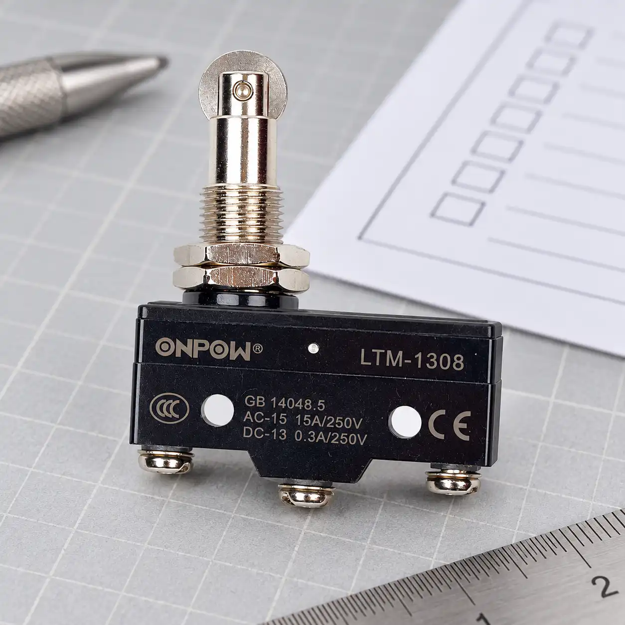
Compare open and closed feedback paths
Choosing NO or NC is a control-system decision. The following qualitative table assumes a passive switch connected to a properly documented input. It does not define the actual response of every controller or machine, and it is not a safety-circuit specification.
| Arrangement | Unoperated switch state | Possible use | Fault limitation to review |
|---|---|---|---|
| COM to NO | Rozepnutý | Signal presence when an actuator reaches the sensing point | A broken wire can resemble the unoperated state |
| COM to NC | Sepnutý | Signal disappears when the actuator operates | A shorted or bypassed path can conceal operation |
| Both changeover paths monitored | One closed and the other open, according to the diagram | Compare complementary position information where the controller supports it | Ordinary contacts and basic logic do not automatically achieve a required safety level |
| Independent contacts | Defined separately in the manufacturer table | Separate feedback circuits when the documented device permits it | Common mechanical actuation and shared wiring remain relevant |
A closed healthy path can make certain open-circuit conditions easier to notice, but that observation is narrower than fail-safe. It does not detect every short circuit, contact weld, misalignment, or mechanical failure. Where position feedback protects people, the required devices, architecture, diagnostics, and validation must come from the machine’s safety assessment.
Match the contact to the controller input
A passive limit switch does not provide a voltage by itself. Its contact makes or breaks the circuit supplied by the input module or associated equipment. Confirm input voltage, common reference, sourcing or sinking configuration, input current, and permissible field wiring from the exact controller documentation.
A three-wire electronic sensor uses supply and signal connections differently from a three-terminal mechanical switch. Do not exchange their wiring instructions merely because each has three connections. Also distinguish protective earth, shield, supply return, and input common in the machine drawing. Joining those points without the specified circuit can create unwanted current paths or unreliable feedback.
Long cable runs add practical issues: cable damage, routing near noisy conductors, terminal retention, and leakage or interference in the input circuit. Use the controller and machine documentation to determine permitted cable construction and routing. If an input filter is used, its delay must be compatible with the machine’s position and stopping requirements.
Contact bounce can produce several electrical transitions during one mechanical operation. The průvodce odstraňováním chyb při odskoku spínače explains that signal issue. Filtering should address a defined input behavior, not conceal an incorrectly positioned actuator or bypass the required response of a safety-related function.
A relay coil is a different load from a logic input
If a limit contact operates a relay or contactor coil, check the exact operational rating for that load. A current value appropriate to a resistive load does not establish suitability for an inductive coil, a different voltage, or a different switching duty. Confirm the coil’s AC or DC supply and any suppression arrangement already included in its socket or driver.
cURL Too many subrequests by single Worker invocation. To configure this limit, refer to https://developers.cloudflare.com/workers/wrangler/configuration/#limits cURL Too many subrequests by single Worker invocation. To configure this limit, refer to https://developers.cloudflare.com/workers/wrangler/configuration/#limits cURL Too many subrequests by single Worker invocation. To configure this limit, refer to https://developers.cloudflare.com/workers/wrangler/configuration/#limits.
cURL Too many subrequests by single Worker invocation. To configure this limit, refer to https://developers.cloudflare.com/workers/wrangler/configuration/#limits.
Contact wiring cannot correct bad actuator placement
cURL Too many subrequests by single Worker invocation. To configure this limit, refer to https://developers.cloudflare.com/workers/wrangler/configuration/#limits.
cURL Too many subrequests by single Worker invocation. To configure this limit, refer to https://developers.cloudflare.com/workers/wrangler/configuration/#limits.
cURL Too many subrequests by single Worker invocation. To configure this limit, refer to https://developers.cloudflare.com/workers/wrangler/configuration/#limits limit switch actuator types guide a micro switch versus limit switch comparison. cURL Too many subrequests by single Worker invocation. To configure this limit, refer to https://developers.cloudflare.com/workers/wrangler/configuration/#limits.
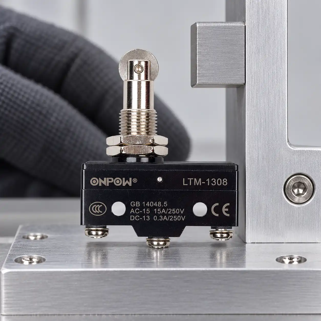
Apply the actual product documentation carefully
Produktová stránka relé ONPOW LTM-1308 product page cURL Too many subrequests by single Worker invocation. To configure this limit, refer to https://developers.cloudflare.com/workers/wrangler/configuration/#limits.
The public page contains general operating and environmental information, but some operation-frequency fields are incomplete. Do not fill those missing values from another model or use a printed photograph to approve a switching rate. Request the current contact drawing, operational load ratings, terminal instructions, actuator travel, and permitted duty for the exact order.
The product page lists an IP designation, but installed protection depends on the model, wiring entry, enclosure, and mounting arrangement. Water resistance does not establish outdoor suitability, chemical compatibility, or washdown performance for a complete machine. Ask for the evidence relevant to the actual environment rather than translating one protection code into a broad durability claim.
Isolate, test, and record the complete feedback chain
Under the approved safe-work condition, confirm the switch identity and contact states first. 29 CFR 1910.333 provides United States electrical-work context for de-energizing and verification; local rules and machine-specific procedures still govern the work. Qualified personnel must establish that condition before electrical identification or changes.
During controlled commissioning, test the installed actuator movement, the electrical contact, the controller indication, and the machine response as separate checkpoints. Verify both approach and release. A screen showing position reached is not enough if the machine overshoots, cannot reset correctly, or handles a cable fault contrary to the approved specification.
For safety-related applications, 29 CFR 1910.212 machine guarding describes guarding obligations in its jurisdiction. It does not approve a particular limit switch. IEC 60947-5-1 gives control-device standards context, also without certifying the device or complete installation by association.
Keep the final terminal map, normal-state definition, actuator drawing, controller input details, expected state sequence, fault-response tests, and replacement order code with the machine. For procurement, send ONPOW the actual application and request the missing model-specific information before releasing a wiring design.
Vzdělávací video
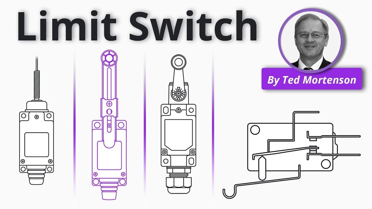
Limit Switch Explained | Working Principles by RealPars. General limit-switch education; this does not certify the illustrated device or supply its terminal map. Otevřete video na YouTube.
Často kladené otázky
Is COM the same as the controller’s common terminal?
Nutně ne. COM označuje společný kontakt spínacího uspořádání. Společný kontakt řídicího zařízení je elektrický odkaz definovaný dokumentací vstupního modulu.
Je NC vždy nejbezpečnější volbou?
No. NC can help reveal some open-circuit conditions, but it does not detect every fault or make a general switch a validated safety device.
Lze identifikovat pořadí terminálu podle tvaru pouzdra?
Ne. Používejte přesný schéma kontaktů, označení svorek a směr pohledu. Podobné balení mohou mít odlišné mapy svorek.
Lze nahradit mechanický koncový spínač třívodičovým senzorem?
Pouze po přezkoumání jednotlivých požadavků na elektrické rozhraní, napájení, chování signálu, mechanické snímání, reakci na poruchy a konkrétní použití. Samotný počet připojení kompatibilitu nezaručuje.
Jaký je minimální záznam o výměně?
Zachovejte přesný kód objednávky, schéma kontaktů, nastavení pohonu, identifikátory zapojení, konfiguraci vstupů, očekávané stavy a ověřenou odezvu stroje.



