

A push button continuity test can help check whether a documented contact changes between an open and a conducting state under an approved, deenergized test condition. The meter’s beep cannot prove that the switch meets its load rating, has acceptable precision contact resistance or is suitable for a safety function. Start with the exact contact diagram, normal-state table and instrument instructions. Establish safe isolation before testing and avoid interpreting an in-circuit parallel path as the switch’s own contact state. This guide explains how to read the evidence without treating a beep as a complete component certificate.
Define the question before selecting the meter function
Continuity screening asks a limited question about a conducting path under the instrument’s test conditions. It can help identify an unexpected open path, a connection that does not change as intended or a mismatch between the assembly and its drawing. It is not the same task as measuring a low contact resistance accurately or evaluating insulation between separate circuits.
Write down the fault being investigated. “The machine does not respond” is an equipment symptom, while “the identified contact does not change state under the approved check” is a more specific observation. Keeping the distinction prevents a healthy switch from being replaced when the actual problem lies in wiring, control logic or indication.
Use the separate Průvodce měřením kontaktového odporu when the requirement concerns a specified low-resistance value and measurement quality. This article concerns continuity interpretation and its limits, not a substitute method for that more demanding measurement.
Establish the intended contact-state table
Identify the exact operator and contact assembly. Obtain the drawing for the installed order code and confirm its intended action. A maintained operator and a momentary operator do not follow the same return sequence, and a multi-position control can have different contact states in each position.
List each relevant contact pair and its expected state before touching the wiring. NO and NC refer to the defined normal mechanical state. They do not identify the machine’s safe state or establish what a control program will do with the input. COM is a contact identifier in the applicable arrangement, not automatically the negative supply.
The push button terminal configuration explanation provides background on contact arrangements. For the actual check, use the equipment schematic and product diagram rather than transferring terminal positions from an illustration of another model.
Plan safe isolation and a meaningful test boundary
Testing must follow the equipment’s safe working procedure and be performed by competent personnel. Control hazardous energy and any relevant stored energy before selecting resistance, continuity or diode functions. A front-panel stop control is not automatically an isolating device, and an open contact does not establish that the equipment is safe to work on.
Decide what the measurement will include. If other paths remain connected, the meter may detect a route through wiring, another component or the wider circuit. That result can be mistaken for a closed switch contact. The approved procedure should define the boundary clearly and specify any necessary disconnection and restoration steps.
Do not disconnect unidentified conductors simply to obtain a preferred reading. Preserve wire identification and the original arrangement, and reconcile any mismatch with the drawing. A test that leaves the equipment incorrectly reconnected is not a successful maintenance operation, even if the intended contact was eventually identified.
Read the beep as an instrument result
Continuity indication depends on the meter’s documented threshold and response behavior. Different instrument models or functions can use different conditions. Do not assume that a familiar sound means the same resistance value on every meter, or that the beep confirms a connection is good enough for every application.
Check the instrument instructions, leads and selected function before interpreting the result. Record the actual meter model where the observation matters. If the equipment acceptance procedure requires a displayed resistance or another measurement, a continuity sound alone does not satisfy that requirement.
| Pozorování | Co může doložit | Co nelze určit pouze na základě těchto informací |
|---|---|---|
| Beep across the identified pair | A path within that instrument’s continuity conditions | Suitable contact resistance at the required duty |
| No beep in the expected open state | No indicated path under the selected conditions | Required insulation performance or safe isolation |
| State changes with the operator | Agreement with part of the contact-state sequence | Complete machine function or safety validation |
| Unexpected beep in circuit | A conducting route exists somewhere in the boundary | That the switch contact itself is closed |
| Intermittent indication | A repeatable symptom requiring investigation | A confirmed failure cause without further evidence |
| Different results on two meters | Different observations needing reconciliation | Permission to choose whichever result passes |
cURL Too many subrequests by single Worker invocation. To configure this limit, refer to https://developers.cloudflare.com/workers/wrangler/configuration/#limits.
Separate the contact from the illumination circuit
cURL Too many subrequests by single Worker invocation. To configure this limit, refer to https://developers.cloudflare.com/workers/wrangler/configuration/#limits.
cURL Too many subrequests by single Worker invocation. To configure this limit, refer to https://developers.cloudflare.com/workers/wrangler/configuration/#limits.
The cURL Too many subrequests by single Worker invocation. To configure this limit, refer to https://developers.cloudflare.com/workers/wrangler/configuration/#limits cURL Too many subrequests by single Worker invocation. To configure this limit, refer to https://developers.cloudflare.com/workers/wrangler/configuration/#limits.
Observe the intended sequence rather than one convenient position
cURL Too many subrequests by single Worker invocation. To configure this limit, refer to https://developers.cloudflare.com/workers/wrangler/configuration/#limits.
cURL Too many subrequests by single Worker invocation. To configure this limit, refer to https://developers.cloudflare.com/workers/wrangler/configuration/#limits.
cURL Too many subrequests by single Worker invocation. To configure this limit, refer to https://developers.cloudflare.com/workers/wrangler/configuration/#limits.
Decide when a different test is required
cURL Too many subrequests by single Worker invocation. To configure this limit, refer to https://developers.cloudflare.com/workers/wrangler/configuration/#limits.
Insulation questions are different again. An ordinary open indication does not demonstrate the required resistance under a specified insulation-test condition. Similarly, continuity does not certify electrical endurance, load-category suitability, environmental protection or approval for a safety-related control function.
When the fault concerns actual machine behavior, follow the equipment’s diagnostic process beyond the switch. A correct contact transition may still be followed by a wiring, input or logic problem. Any necessary energized testing requires separate planning and controls; this article does not provide a live-probing procedure.
Use the real product reference appropriately
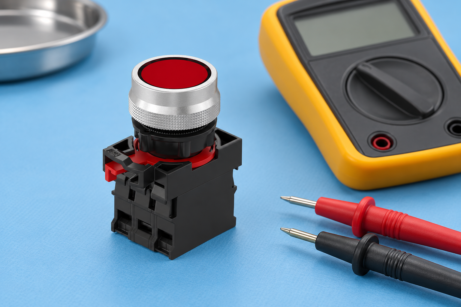
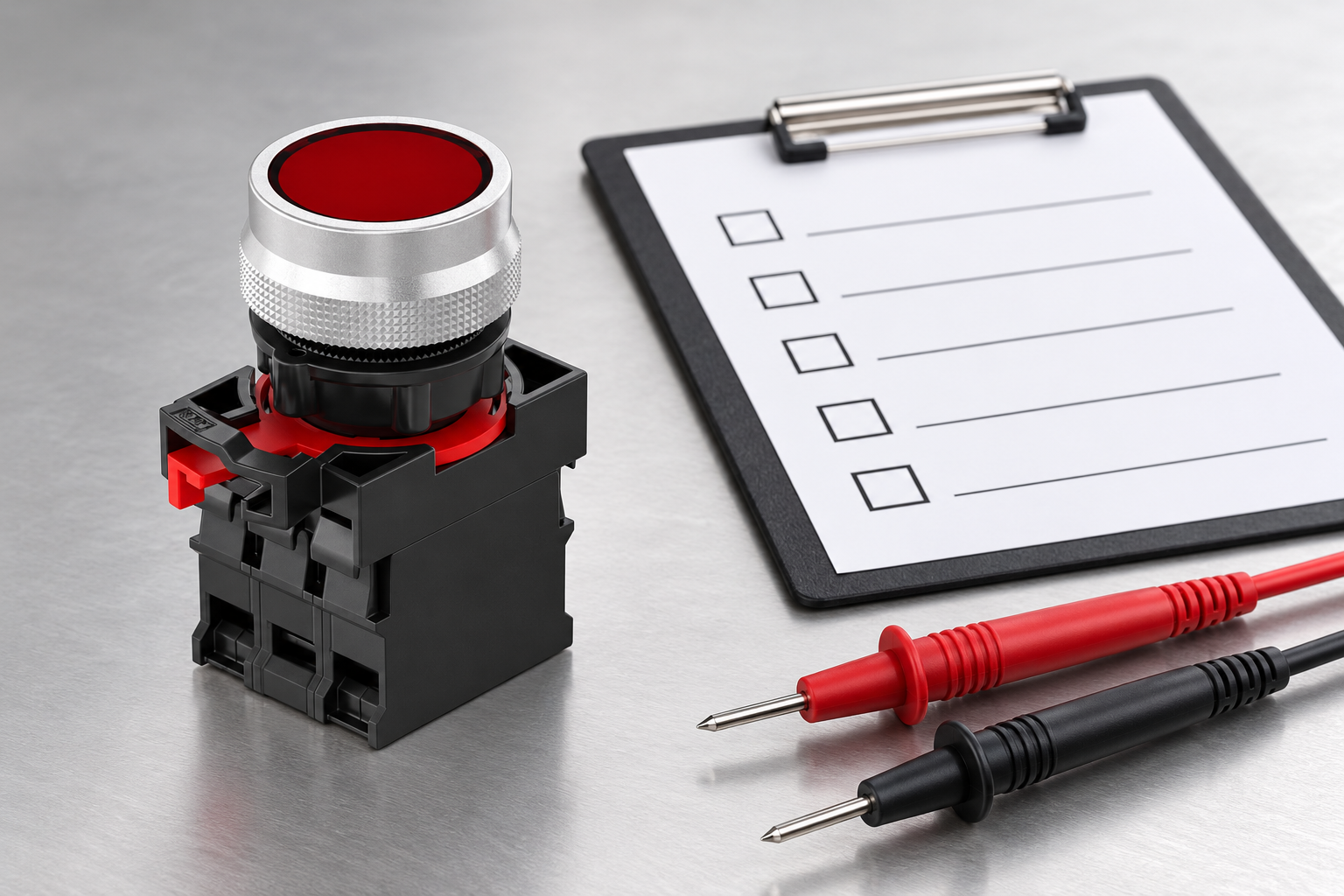
The Sestava ONPOW26-11 illustrates an actual operator and rear contact-component form. The article photographs show an intact, unconnected product and separate test equipment. They do not identify terminals, depict an approved measurement connection or assign an acceptance value to the device.
Obtain the current contact drawing and permitted test information for the exact configuration. If the assembly contains optional blocks or a lamp module, include those in the identification record. Do not assume that a photograph of a similar operator proves the installed rear arrangement.
For related fault investigation, consult industrial push button sticking. That guide separates physical movement from contact state and control response, helping prevent an electrical observation from being misreported as a mechanical defect.
Keep an evidence record and restore the equipment correctly
Record the product identity, contact pair, expected sequence, instrument, test boundary and observations. Keep “no beep,” a displayed value and a confirmed acceptance decision as separate entries when appropriate. This avoids turning an incomplete observation into a retrospective claim that the component passed every required test.
Document any conductors or components disconnected under the approved procedure and verify restoration before the equipment is released. Confirm identification, connections and the required machine functional checks. Where a safety function is involved, complete its applicable validation rather than relying on the continuity screen.
Contact ONPOW with the exact code, contact diagram and recorded symptom if the observed behavior does not match the documented sequence. A clear record supports a useful technical response and reduces the chance of replacing the wrong component or repeating an unsuitable test.
Často kladené otázky
Does a continuity beep prove the switch is good?
Potvrzuje pouze omezené pozorování definované měřicím přístrojem a hranicemi testu. Neprokazuje schopnost spínat zátěž, přesný kontaktní odpor, izolační vlastnosti, životnost ani celkovou vhodnost zařízení.
Proč může otevřený spínač v obvodu stále způsobovat pípnutí?
Do měření může být zahrnuta i jiná propojená cesta. Schválený postup musí přesně definovat, co se měří, aby nedošlo k záměně vlastního stavu spínače se stavem širšího obvodu.
Znamená absence zvukového signálu totéž jako úspěšně provedená zkouška izolačního odporu?
No. Insulation performance requires its specified method, conditions and acceptance requirements. An ordinary continuity function does not provide that evidence.
Can I check an illuminated button without its diagram?
Do not assume a pinout. Identify the contact and illumination circuits from the exact product information, and use the applicable safe test procedure for the function being investigated.
Odkazy a rozsah
Bezpečnost údržby elektrických zařízení HSE provides the safe-work framework. The Fluke 12 manual a Manuál multimetru izolace Fluke provide examples of instrument-specific continuity and other measurement functions. Their settings and limits must not be copied into an ONPOW acceptance specification or treated as universal meter behavior.
Další informace
Vzdělání v oblasti elektrických měření a omezení přístrojů. Toto je další vzdělávání, nikoliv schéma zapojení specifické pro model, testovací napětí, mezní hodnota přijetí nebo povolení k testování napájeného zařízení.
NPTEL: Elektrické měření a elektronické přístroje — NPTEL IIT Kharagpur



