

A momentary key switch returns to its designated rest position when the operator releases the key. It suits commands that should exist only while someone deliberately turns or holds the operator, such as a supervised adjustment or a reset request. A maintained key switch instead stays in the selected position. Specify the return direction, contact sequence, permitted key removal positions and intended controller response separately. The word “momentary” does not establish a safety function, an electrical rating or permission to restart equipment. Before ordering, match the exact switch drawing and the machine’s control requirements rather than relying on a photograph or the number of keys supplied.
What spring return changes in the control sequence
Consider a control panel with a neutral position and a clockwise command position. A spring-return operator can make a contact while it is held clockwise and release that contact when the key is let go. That physical action creates a temporary electrical request. It does not, by itself, determine whether the controller interprets the request as a pulse, a maintained input or an acknowledgement. The contact table and the control program must agree.
For a supervised adjustment, a temporary request can prevent the command from remaining selected after the operator lets go. For a reset input, the controller may require a new transition after a fault is cleared. Neither example proves that an ordinary key switch provides an enabling-device function. The required machine safeguards, interlocks and control behavior need their own assessment.
A return spring also does not guarantee that the electrical contact will always change correctly. Mechanical damage, unsuitable installation, contact wear and an incorrect assembly can undermine the intended action. Treat the operator movement and the contact response as two things to verify during acceptance.
Momentary and maintained positions can coexist
A three-position operator may have a maintained position on one side and a spring-return position on the other. Another version may return to the center from both directions. These are different purchase specifications even if the heads look identical. Drawings sometimes indicate spring return with arrows or parentheses, but the supplier’s legend remains the authority for that device.
Write the requested behavior in ordinary language as well as in a code: “center rest; clockwise returns to center; counterclockwise stays selected,” for example. Attach the corresponding contact-state table. This reduces the chance that a supplier, panel builder and commissioning engineer interpret the same shorthand differently.
Do not assume that a two-position operator can return to an arbitrary position. Its rest state, rotation direction and available travel depend on the supplied mechanism. Ask for the actual version drawing before using it to finalize a control design.
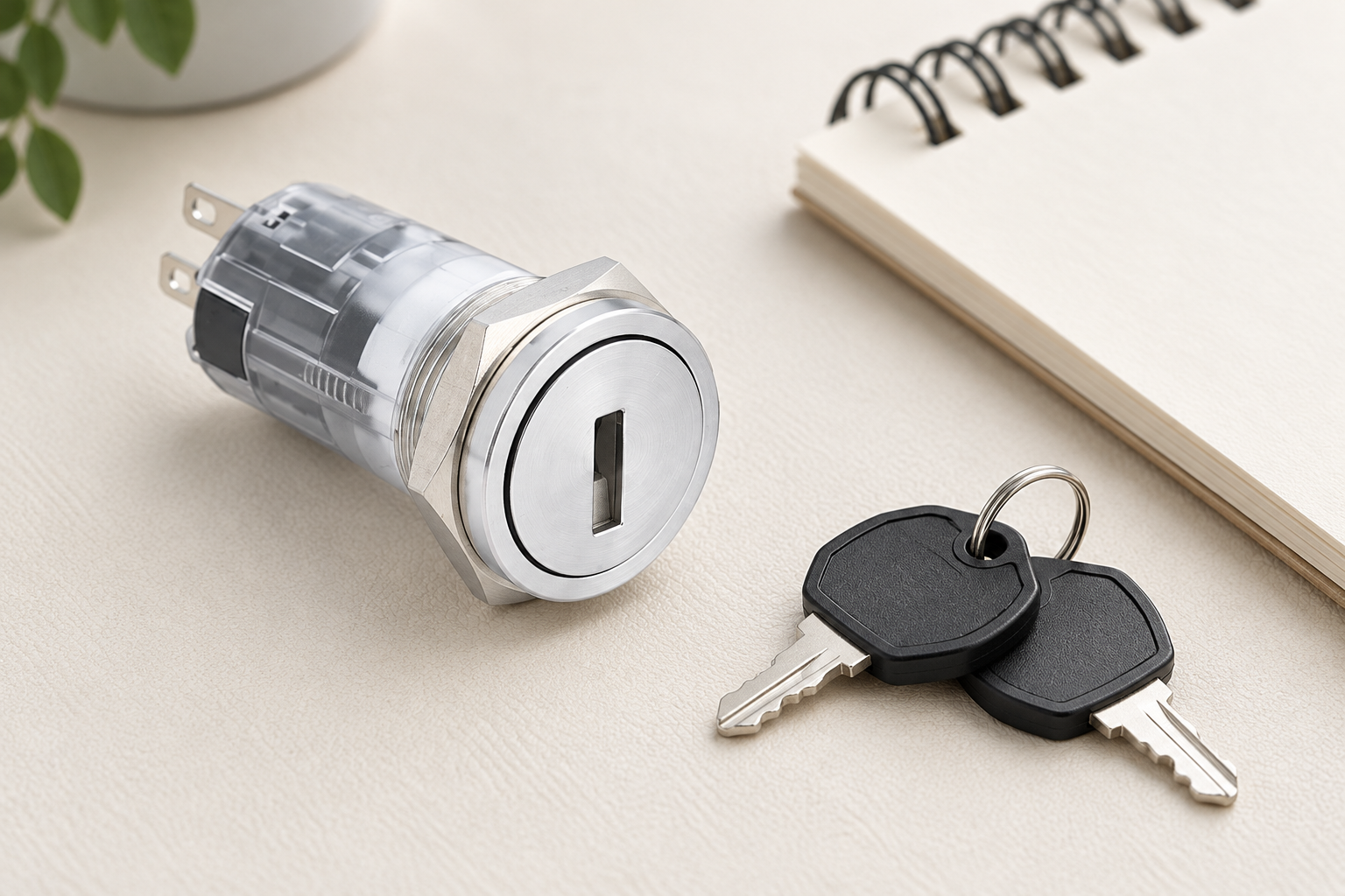
A practical decision table for the ordering brief
The following table is a specification checklist, not a wiring prescription. Its purpose is to separate the choices that buyers often collapse into one phrase such as “momentary key switch.” Electrical work and commissioning belong with qualified personnel using the complete machine documentation.
| Pregunta de selección | Information to request | Why it affects the result |
|---|---|---|
| Where should the operator rest? | Named rest position and rotation diagram | The controller needs an unambiguous state after release |
| Which directions return automatically? | Return arrows for every non-rest position | One side may be maintained while another is momentary |
| What happens to each contact? | Terminal labels and position-by-position contact table | Physical movement does not establish the required input sequence |
| Where may the key be removed? | Explicit removal positions for the exact lock version | Removal permissions affect who can leave or change a selected mode |
| What electrical signal is switched? | DC or AC duty, load type, input current and ratings | A pilot contact rating cannot be inferred from an operator photograph |
| What happens on power restoration? | Documented controller and restart behavior | A released key must not be treated as permission for unexpected motion |
| How will the panel be assembled? | Cutout, panel thickness, retention method and rear clearance | Binding or loose installation can interfere with reliable operation |
For existing equipment, compare this list with the approved schematic and original bill of materials. A convenient replacement that changes just one row may still change the behavior of the entire machine.
Contact tables matter more than terminal counts
A switch with one normally open contact and one normally closed contact has two contact functions. That description alone does not establish which positions activate them, whether both functions share a common terminal or how contact transition occurs during rotation. Use the actual contact diagram and terminal markings.
Specify the state in the rest position first. Then specify the state while held in each command position. Finally, describe the expected state after release. This three-step description helps reveal discrepancies between a mechanical spring-return claim and the required electrical request.
El ONPOW key and selector switch range provides the product starting point. For a broader explanation of contact layouts, see two-position selector contact logic. These resources support the selection process; the exact drawing supplied with the ordered switch still decides its connections.
When a controller input has a small operating current, verify that the contact is suitable for that signal duty. A high conventional current figure is not evidence of dependable switching at every low-current input condition. Ask for the relevant minimum-load information or approved input application instead of inventing a lower limit.
Key removal is a separate requirement
Spring return describes what happens when rotational force is released. Key removal describes where the lock permits the key to be withdrawn. A switch can return automatically yet permit removal only at rest. Another version can impose different restrictions. Never infer removal positions from a photograph showing a key beside the switch.
For a mode-control application, decide whether the key should remain captive while a particular mode is selected. For a temporary command, decide whether the operator should remove the key only after the command has ended. These choices depend on the machine’s operating procedure and access policy.
A keyed operator is also not a substitute for hazardous-energy isolation. A person holding the key to an ordinary control switch does not necessarily control every energy source. In US workplaces, 29 CFR 1910.147 distinguishes control devices from energy-isolating devices. Apply the relevant local rules and the employer’s documented procedure when servicing equipment.
Choose the controller response deliberately
For a reset request, define what makes the request valid. The controller might need a released input before it can recognize the next request. It might reject a request while another condition remains unsatisfied. These are controller requirements and must not be attributed to the key mechanism.
For a supervised command, define whether motion stops when the contact opens and what other conditions must remain satisfied. Where hazardous motion is possible, ordinary switch selection is only one component of the risk assessment. Do not label the arrangement safe merely because an operator must hold a key.
For a start request, distinguish the momentary input from the subsequent running state. A motor may continue running after a legitimate start pulse because the control system retains a run command. That behavior can be correct for the application, but it is different from hold-to-run operation. The buyer’s specification should identify which behavior is intended.
El two-position key switch guide introduces the maintained-position alternative. Review the three-position selector control explanation when the panel uses multiple modes; confirm the final drawing rather than assuming those examples map to a keyed version.
Installation details that can hide a correct specification
A correct return mechanism can feel wrong after an unsuitable installation. An excessively tight mounting arrangement, incorrect panel thickness, damaged head or interference behind the panel can affect operation. Follow the exact mounting instructions and inspect the complete assembly before deciding that the return action itself is faulty.
Rear clearance needs to include terminals, connected conductors and the access required to service them. Do not choose a compact head based only on the visible front diameter. A different contact block can change the depth or terminal direction without an obvious change at the front.
For environments involving moisture, cleaning or dust, request the protection information for the assembled installation. A front-panel rating does not establish rear-terminal protection or suitability for every cleaning chemical. The ONPOW key switch product page is a useful reference for the pictured product family, but it does not confirm every optional return action or application condition.
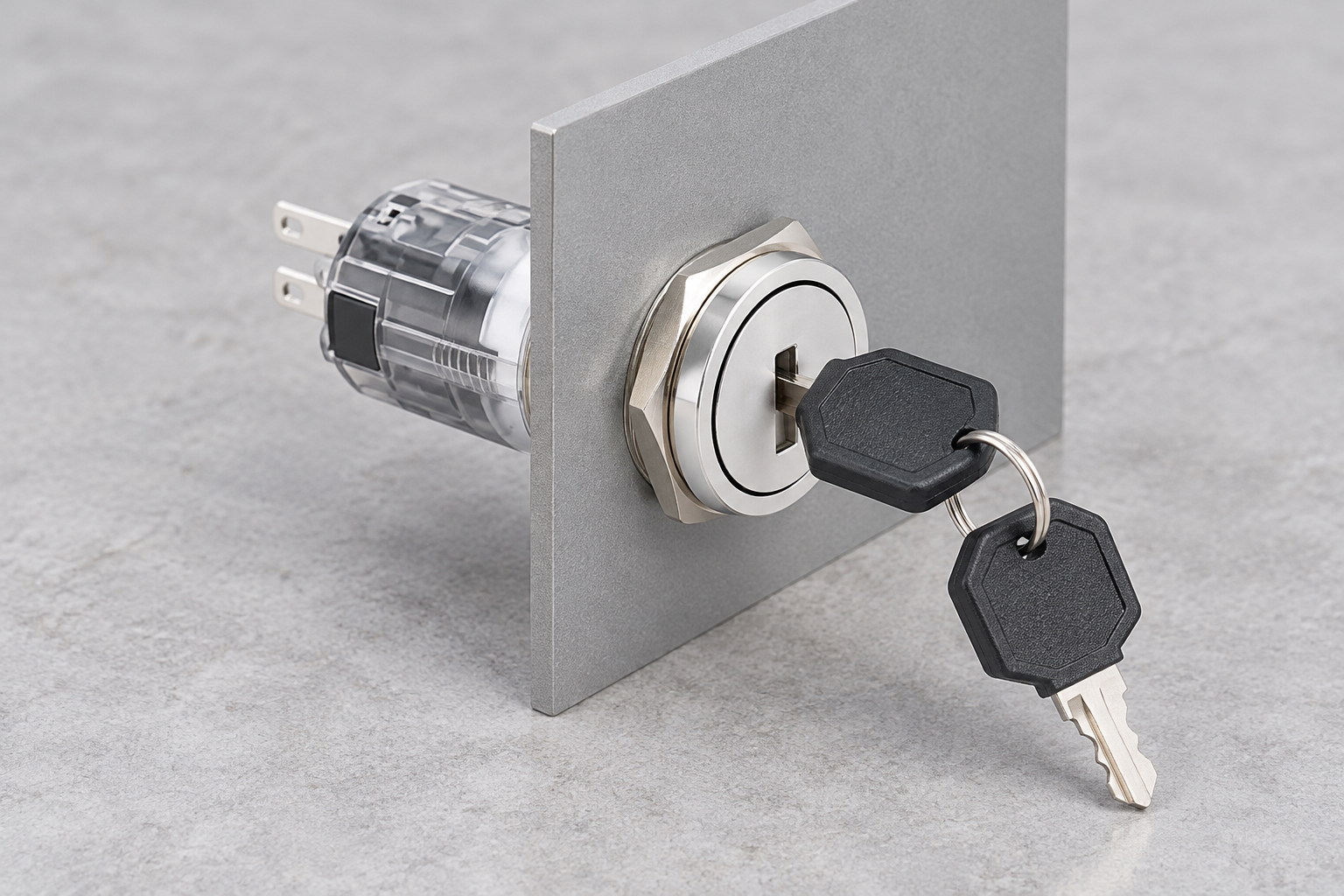
Acceptance checks before handover
Record the delivered part identification and compare it with the approved ordering brief. With the equipment appropriately isolated and under the responsible person’s procedure, verify the mechanical action, key removal permissions and contact states. Do not use a continuity check on an energized circuit or improvise a machine test by bypassing safeguards.
A qualified commissioning process should then check the input behavior against the documented controller sequence. Confirm what occurs after release, after an interrupted request, after a fault and after power restoration. Test conditions and expected results should be approved before the machine is put into service.
The electrical safety requirements in 29 CFR 1910.333 provide US workplace context for deenergization and safe work practices. They are not a universal product certification or a substitute for the machine’s applicable requirements.
Document discrepancies before accepting an alternative part. An operator that rotates correctly but has different contacts, a different removal position or unsuitable electrical duty is not an equivalent replacement. Preserve the final contact table and commissioning record so that the next replacement does not repeat the same uncertainty.
Further learning: drawings and controller inputs
The RealPars lesson below explains how a basic wiring diagram relates to a PLC program. Use it to understand the distinction between a physical contact and a controller decision. It does not establish the behavior of an ONPOW key switch or validate a machine safety function.

Questions buyers commonly ask
Is a momentary key switch the same as a maintained key switch?
No. A momentary position returns when rotational force is released; a maintained position stays selected. Some operators combine the two actions. Request the position diagram and contact table for the exact supplied version.
Can the key be removed while the switch is held?
That depends on the lock and removal-position specification. Spring return does not establish key removal permissions. Obtain written confirmation for each position before ordering.
Does spring return make a key switch an emergency stop?
No. Spring return alone does not define an emergency-stop device or safety function. Select equipment against the machine’s requirements and applicable assessment rather than assigning a safety role from its mechanical action.
Can a high-current key switch reliably operate a small PLC input?
A high-current figure alone does not answer that question. Verify the contact’s signal-duty suitability, the input requirements and any specified minimum load. Do not infer low-current performance from a conventional rating.
What should I send with an inquiry?
Send the rotation and return diagram, contact table, removal positions, electrical duty, mounting requirements and intended controller response. Ask ONPOW to confirm the exact available configuration before using a quotation as the final machine specification.



