

Push button contact block replacement starts with the identity of the complete assembly, not the diameter of the front button. Record the operator, mounting holder, rear block, contact function and circuit duty before requesting a replacement. Keep the existing head only when the manufacturer confirms that the proposed block and holder are approved for it. A similar latch, matching color or apparently identical terminal spacing does not establish interchangeability. This guide covers replacement documentation and acceptance checks; it does not provide a universal disassembly procedure or a cross-brand substitution list.
Establish whether replacement is the right repair
A machine that ignores a button does not necessarily have a defective contact block. The operator may not transmit its full movement, a mounting holder may be loose, a wire may have failed, or the machine input may be behaving correctly while downstream logic prevents operation. Replacing the rear block without distinguishing these conditions can hide the fault temporarily and leave the underlying problem in place.
Begin with the reported symptom and the circumstances in which it occurs. Does the button feel different? Does the machine input change while the commanded action fails? Did the issue start after panel work or a change of cleaning process? Preserve the observations before dismantling anything. Testing and isolation should be performed by competent personnel following the equipment’s approved procedure. A stop button is not an energy-isolating device.
For general component selection, use the separate push button contact block guide. Here the decision is narrower: whether an existing operator can remain while its rear switching component is replaced without changing the intended assembly or machine function.
Capture the assembly identity before ordering
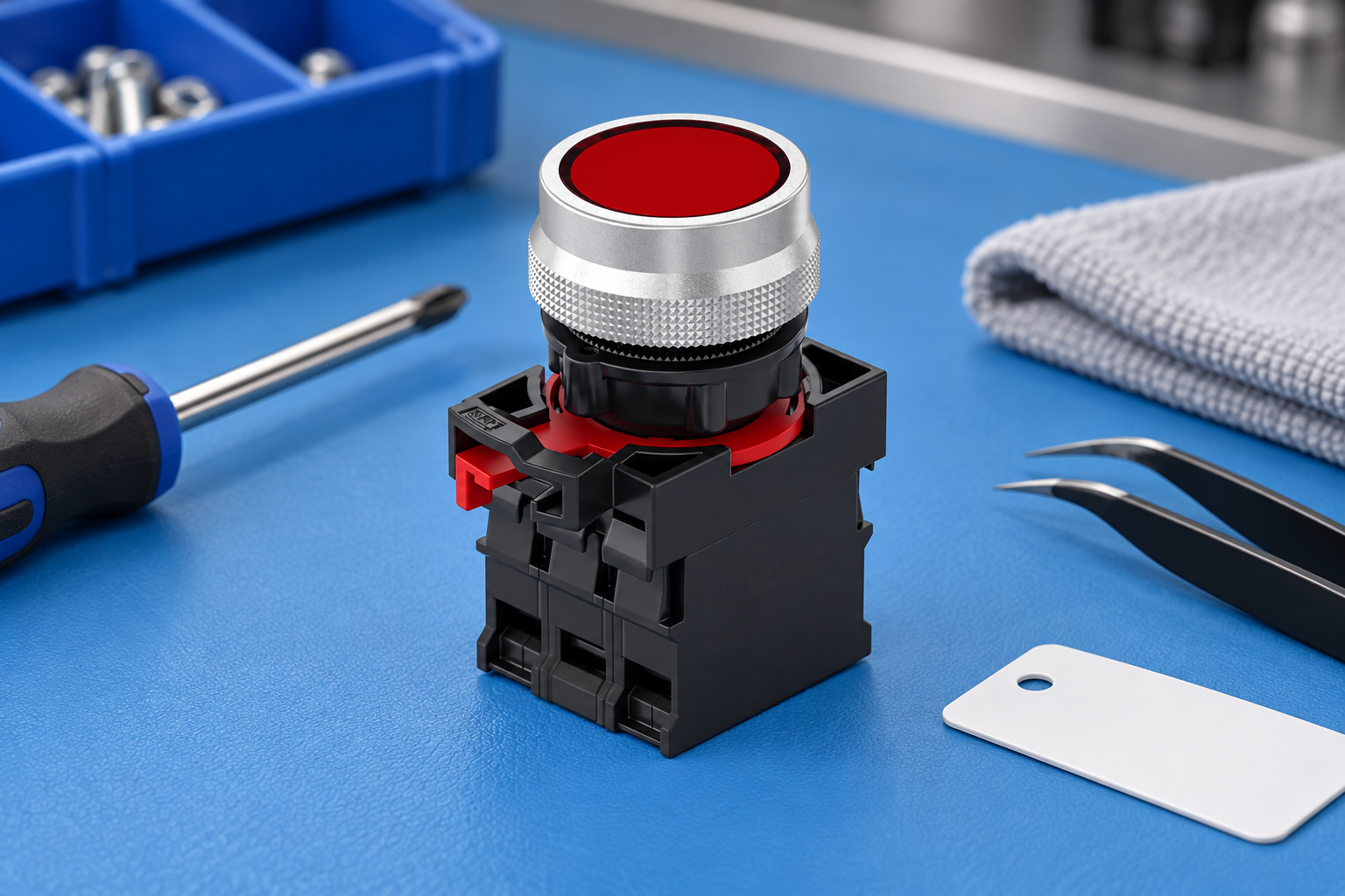
Photograph the front operator, rear holder, markings, contact blocks and wire labels before removing components. Take a view that shows the relationship between parts as well as close views of readable order codes. Record the equipment drawing reference and revision. A photograph of the button face alone usually cannot identify the rear mounting arrangement or electrical configuration.
Keep separate fields for the complete-device code and each subcomponent code. A procurement system may list a complete switch under an internal part number while the replaceable block has its own manufacturer’s designation. Ask whether a supplier quotation describes the complete assembly, an operator only, a holder or a contact block. These are different deliverables even when sellers use similar product photographs.
If markings are unreadable, identify the equipment manufacturer and original bill of materials before guessing. Do not select a block solely because it clips into place during an informal trial. Retention, travel, release and applicable ratings still require documented confirmation. Preserve the old part for comparison and failure investigation unless the site’s contamination or safety procedure requires another disposition.
Build a replacement evidence table
The following table is a qualitative purchasing checklist, not a declaration of compatibility between particular ONPOW parts. Obtain the applicable drawing, instructions and approved combinations for the exact order codes.
| Evidence | Record for the installed assembly | Require for the replacement |
|---|---|---|
| Operator and holder | Manufacturer, family, codes and revision | Explicit approved pairing |
| Contact function | Normal and operated states for each circuit | Matching documented switching sequence |
| Block arrangement | Quantity, positions and permitted stack | Approved location and stack configuration |
| Electrical duty | Actual voltage, load category and control current | Suitable ratings including any minimum-load limit |
| Connections | Conductor type, terminal style and preparation | Applicable wire range and assembly instructions |
| Mechanical envelope | Rear depth, wire route and access | Clearance with the door and other devices |
| Safety function | Equipment function and validation record | Required device claims and system revalidation |
An unanswered row is a purchasing question rather than permission to assume equivalence. Request a written response linked to the exact product configuration. Keep that response with the replacement record so that the next service team does not have to reconstruct the decision.
Check contact behavior independently of appearance
Normally open and normally closed describe contact states relative to the mechanism’s defined normal position. They do not, on their own, establish what the machine will do. The circuit drawing, operator action and control logic determine the resulting function. An illuminated operator can also include a separate lamp circuit that must not be confused with a switching contact.
Record a before-and-after state table for every affected circuit. Include the released state, each operated position and the return behavior. Where the equipment uses monitoring or redundant channels, preserve the approved architecture and validation requirements. A basic continuity check cannot demonstrate that a safety-related assembly meets its required function or that a replacement has positive-opening characteristics.
For an example of a real modular product form, consult the ONPOW26-11 product page. Its photograph helps identify the operator, holder and rear component relationship. It is not evidence that a particular loose contact block fits another ONPOW device or any other manufacturer’s operator.
Preserve the wiring record and termination quality
Before disconnecting conductors, record terminal identifiers and wire labels against the drawing. Do not rely on wire color as the only identification method. Separate the physical terminal location from its electrical function: the location can change between product revisions even when the intended circuit remains the same. Stop and reconcile any discrepancy rather than transferring wires by visual position.
Use the replacement terminal’s instructions for conductor material, preparation, permitted end treatment and tightening method. A ferrule, solder-tinned end or second conductor is not automatically permitted because it was present in the old installation. Reterminate damaged conductors only through the site’s approved process, preserving adequate service length and strain relief.
Do not use the contact block as a support for a heavy wire bundle. Route and restrain conductors so that opening the panel door or performing adjacent maintenance does not pull on the terminals. The terminal configuration explanation is useful for understanding circuit arrangements; it does not replace the exact assembly instructions.
Use the manufacturer’s removal and installation sequence
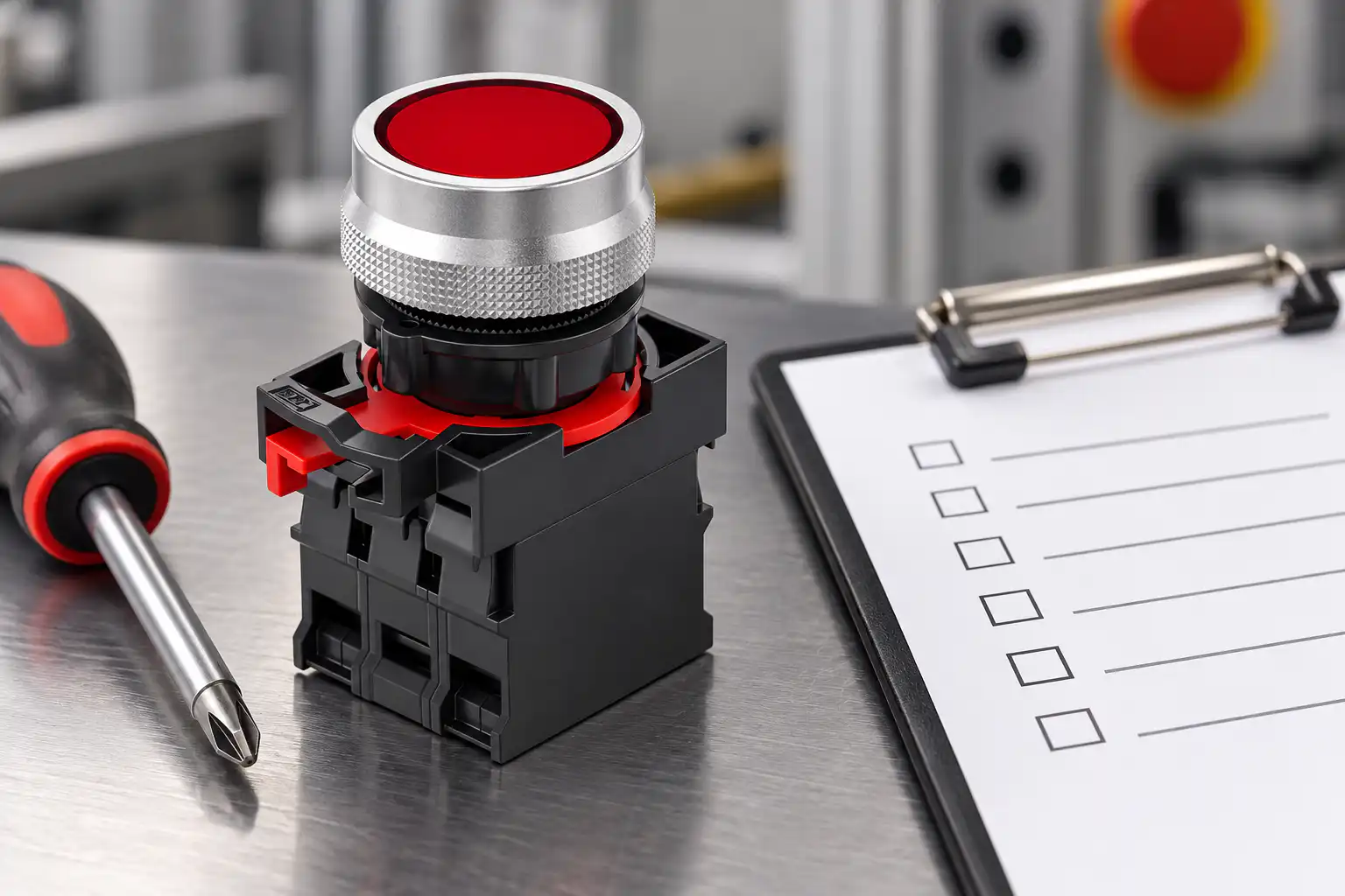
Modular blocks can use different clips, holders and release features. Obtain the correct procedure rather than prying against a feature that resembles a latch. Some assemblies require removal in a particular order or restrict how blocks may be stacked. Forcing an incompatible part can damage the holder while leaving the assembly apparently secure.
After installation, inspect the complete mechanical relationship. The block should be retained as the instructions specify, the operator should move and return correctly for its intended action, and no conductor should obstruct movement. Check the surrounding equipment as well: cable duct lids, enclosure hardware and the closed door must not press on the rear assembly.
If the holder or operator is damaged, replacing only the block may be inappropriate. Escalate the scope of repair and obtain a complete approved assembly when necessary. Do not preserve an old head merely to avoid changing a visible panel component if doing so leaves an unverified or mechanically compromised combination.
Verify the repair before restoring normal operation
Plan acceptance checks before making the change. First inspect identification, installation and terminations under the site’s safe working procedure. Then verify the documented contact-state sequence using a suitable method. Any energized functional testing must be specifically justified, controlled and performed by competent personnel under the equipment’s procedure.
During controlled functional checks, distinguish the contact output, control input, indication and machine action. An indicator lighting does not prove that the correct contact changed or that the intended stop behavior is available. Where the replacement affects a safety function, complete the required system checks before returning the machine to production.
Record the replacement code, installation date, technician, drawing revision, observed fault and acceptance results. Retain a sample or photographs of the failed part if the failure is repeated. Repeated damage may point to load duty, environment, assembly stress or maintenance practice rather than a sequence of unrelated defective blocks.
Order a traceable replacement rather than a visual match
A useful inquiry states the installed operator and holder, existing block code, required contacts, application duty, wire information and available rear space. Add readable photographs and the relevant drawing extract. Ask the supplier to identify any required holder change and whether the proposed supply is a component or a complete assembly.
For wider procurement checks, see incoming inspection for push buttons and contact resistance measurement. These address receiving and measurement quality separately from the mechanical interchangeability decision. Contact ONPOW with the exact codes and photographs when a matching replacement cannot be established from the available documentation.
Frequently asked questions
Can I replace a contact block while keeping the old operator?
Sometimes, when the manufacturer approves the operator, holder and replacement block combination and the retained parts remain serviceable. A common panel hole diameter does not establish compatibility. Obtain the exact pairing before purchasing or installing the part.
Does the same NO or NC marking make two blocks interchangeable?
No. The marking addresses contact state, while mechanical retention, operating travel, electrical duty, terminal requirements and assembly approvals can differ. Match the complete set of requirements rather than a single marking.
Should a replacement block be tested only with a multimeter?
A suitable deenergized check can help confirm contact behavior, but it does not establish complete machine performance or safety-function suitability. The repair requires installation inspection and the equipment’s applicable functional and validation checks.
What if the original part number is no longer available?
Request a documented successor or an approved complete-assembly replacement from the equipment or component manufacturer. Treat changes to the operator, holder, contact arrangement or control behavior as an engineering change requiring appropriate review.
References and scope
The UK’s HSE guidance on safe electrical maintenance supports competent maintenance and suitable precautions. Its work equipment maintenance guidance explains the importance of planned, safely performed maintenance. Neither source approves an ONPOW part combination; product compatibility and installation details must come from the exact manufacturer’s documentation.
Further learning
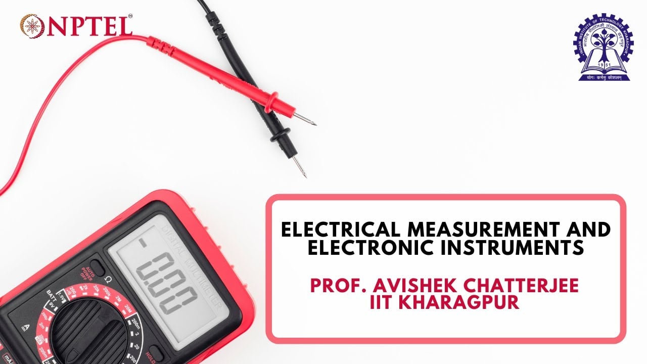
University background on electrical measurement, supporting the distinction between an observation and a verified contact-state result. This is not a replacement or live-testing procedure for the illustrated switch.
NPTEL: Electrical Measurement and Electronic Instruments — NPTEL IIT Kharagpur



