

A 3 position selector switch wiring diagram for Hand–Off–Auto should define which contact closes in Hand, which closes in Auto, and what happens in the center position. Three handle positions do not guarantee a universal contact arrangement or terminal map. A typical design uses separate manual and automatic requests, with neither request active in Off, but the exact switch assembly and machine logic must be verified. This guide explains how to create and check that contact plan without guessing pin numbers. It addresses ordinary operating modes; an HOA selector is not, by itself, an isolator, emergency stop, or validated safety system.
Write the mode behavior before drawing the wires
Hand, Off, and Auto are names for machine behavior. In Hand, an operator may request operation directly. In Auto, a process command may request it when conditions permit. In Off, neither path should request operation if that is the approved design. The labels alone do not establish which controller inputs, relay coils, or power circuits implement those states.
For example, a tank transfer pump might have a manual request for supervised filling and an automatic request controlled by a level signal. Both operating paths can still depend on permissives such as overload status and the process limits defined by the design. Hand should not be assumed to bypass every protection just because its command does not originate from the automatic process.
Describe what happens when the operator changes mode while the machine is running. Does the equipment stop before accepting a new request? Can it continue if an Auto request remains present? Is acknowledgement required after a fault or power interruption? Answer those questions in the functional specification before choosing contact blocks. The final circuit must implement the required behavior, including any safeguards identified by the machine assessment.
Separate mechanical positions from electrical contacts
An operator can have three positions with several different contact combinations. The center may open both request paths, close a separate indication contact, or behave differently in an application-specific assembly. A handle photo cannot establish that combination. Obtain the contact table for the complete switch order code, including its contact blocks and operating action.
Maintained positions stay selected after release. Spring-return positions return to another position after release. A maintained Hand–Off–Auto sequence and a spring-return manual command are not interchangeable. Also confirm whether the direction is described from the operator side or from the terminal side. A mirrored drawing can turn a correctly manufactured assembly into an incorrectly labeled machine function.
The switch diagram should identify every electrical contact pair independently. Avoid a vague note such as connect the left terminal to Hand: left changes with view direction and panel access. Use the manufacturer’s terminal references and the machine’s conductor identifiers. If documentation is incomplete, pause the design release rather than borrowing a wiring map from an apparently similar operator.
Build a truth table for the intended HOA requests
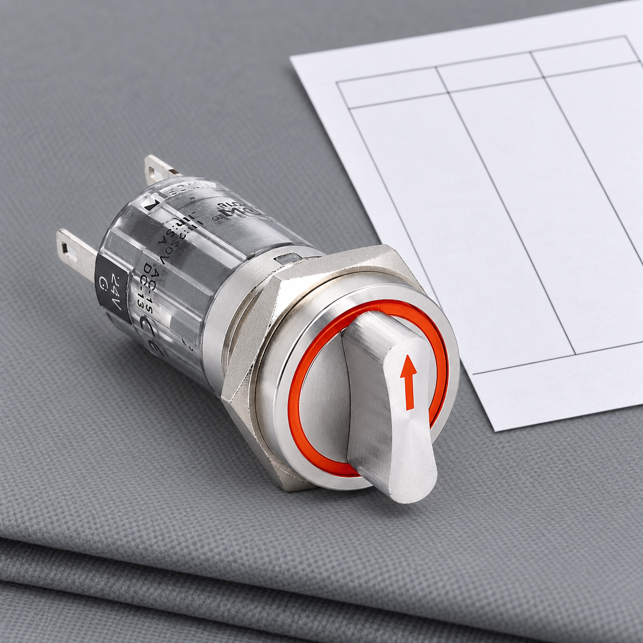
A truth table makes the required steady states explicit before connections are made. The example below uses two independent request contacts and a center position that opens both. It does not specify the actual contacts or terminal numbers of the photographed ONPOW selector. Confirm whether the ordered assembly can implement the chosen requirements.
| Selected mode | Manual request path | Automatic permission path | Required application check |
|---|---|---|---|
| Hand | Closed | Open | Manual command remains subject to approved permissives |
| Off | Open | Open | Neither mode path requests operation; other energy sources may remain |
| Auto | Open | Closed | Operation requires the automatic command and approved permissives |
| Transition between positions | Defined by the contact mechanism | Defined by the contact mechanism | Review any overlap or interruption against the controller design |
Do not convert this table into a claim that every three-position selector has two normally open contacts. Some applications require additional status contacts or a different contact timing arrangement. The table expresses the machine requirement; the supplier drawing demonstrates what the actual assembly does.
A separate mode-status input can help distinguish a selected mode from a run command, but it does not automatically provide fault detection. If two signals must never be accepted together, define how the controller handles that combination and validate the physical contact arrangement. Software assumptions should not conceal an incompatible switch assembly.
Controller-input wiring and relay wiring need different checks
With a controller input, the selector generally switches an input signal. Determine the input supply, common reference, sinking or sourcing arrangement, permitted contact characteristics, and field-wiring rules from the exact module documentation. The Hand and Auto contacts may feed distinct inputs, but sharing a common must be permitted by that circuit. Do not join separate sources because their nominal voltages happen to match.
With relay or contactor control, the selector may switch a coil circuit. Confirm AC or DC coil supply, coil demand, switching category, and any suppression already installed. The load connected to the relay contacts is a separate circuit. Confusing the coil rating with the load rating can lead to a selector that is mechanically appropriate but electrically unsuitable.
A electromechanical relay wiring diagram guide explains that separation. For a simpler command without an automatic mode, compare the two-position Hand–Off selector guide. Neither article supplies a universal machine wiring instruction; the exact drawings remain essential.
Confirm the transition between Hand and Auto
Steady-state continuity is only part of the contact review. During rotation, one path may open before another closes, or the assembly may have another documented sequence. Check the actual contact timing when the application depends on it. A controller may also see intermediate states depending on input scanning and the contact mechanism.
The acceptable response depends on the process. A mode change on a supervised bench device may have different implications from a moving machine. Define whether a new mode needs a fresh command and whether the machine must stop before accepting it. Do not use a generic break-before-make description to approve an unknown assembly or to claim a safety function.
If a PLC observes both requests briefly, investigate the contact table, transition sequence, wiring, and input logic. Filtering can address a defined signal issue, but it should not be used to hide overlapping commands that violate the functional specification. The input debouncing guide offers related context for evaluating transitions without treating a timing filter as a replacement for correct circuit design.
Use product specifications within their stated scope
The ONPOW LAS1-AGQ16-11X/31/S page identifies a stainless-steel selector package and lists pin terminals measuring 2.8 by 0.5 mm. It also lists front-panel IP40 and IK02 and a maximum nut torque of about 0.6 Nm. Those published details are model-specific; confirm the current drawing, exact assembly, and installation instructions before using them in a panel design.
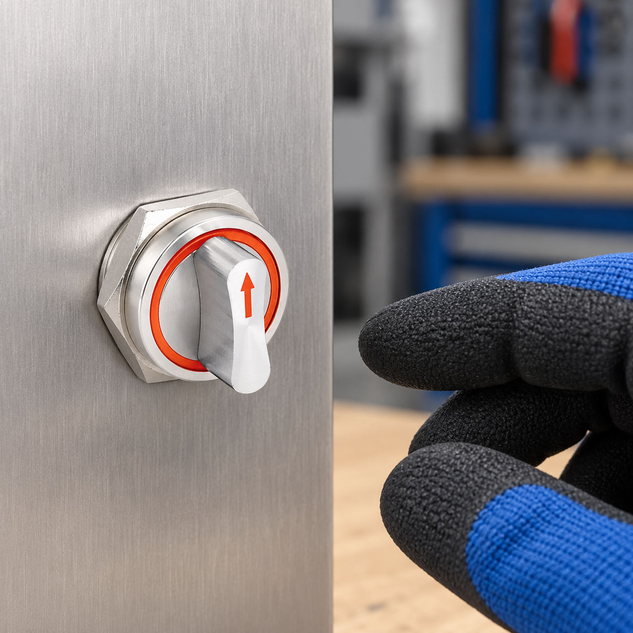
The page’s Ui and Ith entries do not replace the operational rating for a particular coil or input circuit. Request that rating and the complete contact schedule. Do not infer lamp behavior from a colored ring, and do not assume a dry indoor product image proves washdown or outdoor suitability. Any protected installation must be evaluated as an assembly.
IEC 60947-5-1 covers electromechanical control-circuit devices. It provides standards context for device review, not automatic certification of this product or the completed machine. Confirm the current applicable edition, manufacturer declarations, and destination-market requirements with the responsible engineer.
Isolation and an Off command serve different purposes
A center Off position can remove a normal command while electrical, pneumatic, hydraulic, or stored mechanical energy remains. Maintenance requires the isolation and verification procedure appropriate to the equipment. Never use the selector label as the sole evidence that work can begin.
For United States electrical work, 29 CFR 1910.333 addresses de-energizing and verification. Its requirements are not a machine-specific procedure, and other jurisdictions have their own obligations. Qualified personnel must establish the safe work condition before contact checks or circuit changes.
Commission with a mode-by-mode test record
Under approved isolation, verify each contact pair in every stable position and compare the results with the supplier table. Check the label orientation and operator action at the same time. Record unexpected readings rather than changing terminal assignments until the assembly identity and drawing are resolved.
During controlled commissioning, check the controller’s mode indication separately from the machine’s run response. In Hand, test the required manual request and permissives. In Off, confirm both request paths disappear and the approved stopping behavior occurs. In Auto, confirm the process request is necessary and the relevant conditions still govern operation.
Include mode changes, command restoration, power interruption, and fault recovery in the approved test plan. The machine may need acknowledgement before restart even when a maintained selector still indicates Hand or Auto. Retain the final schematic revision, order code, terminal orientation, expected truth table, observed results, and approval record for future replacement.
When buying a selector assembly, send that complete behavior specification along with the panel drawing and environmental requirements. The selector switch types guide helps compare operator families. For the actual assembly, ask ONPOW to confirm contacts, terminal format, action, and ratings against the proposed application.
Educational video
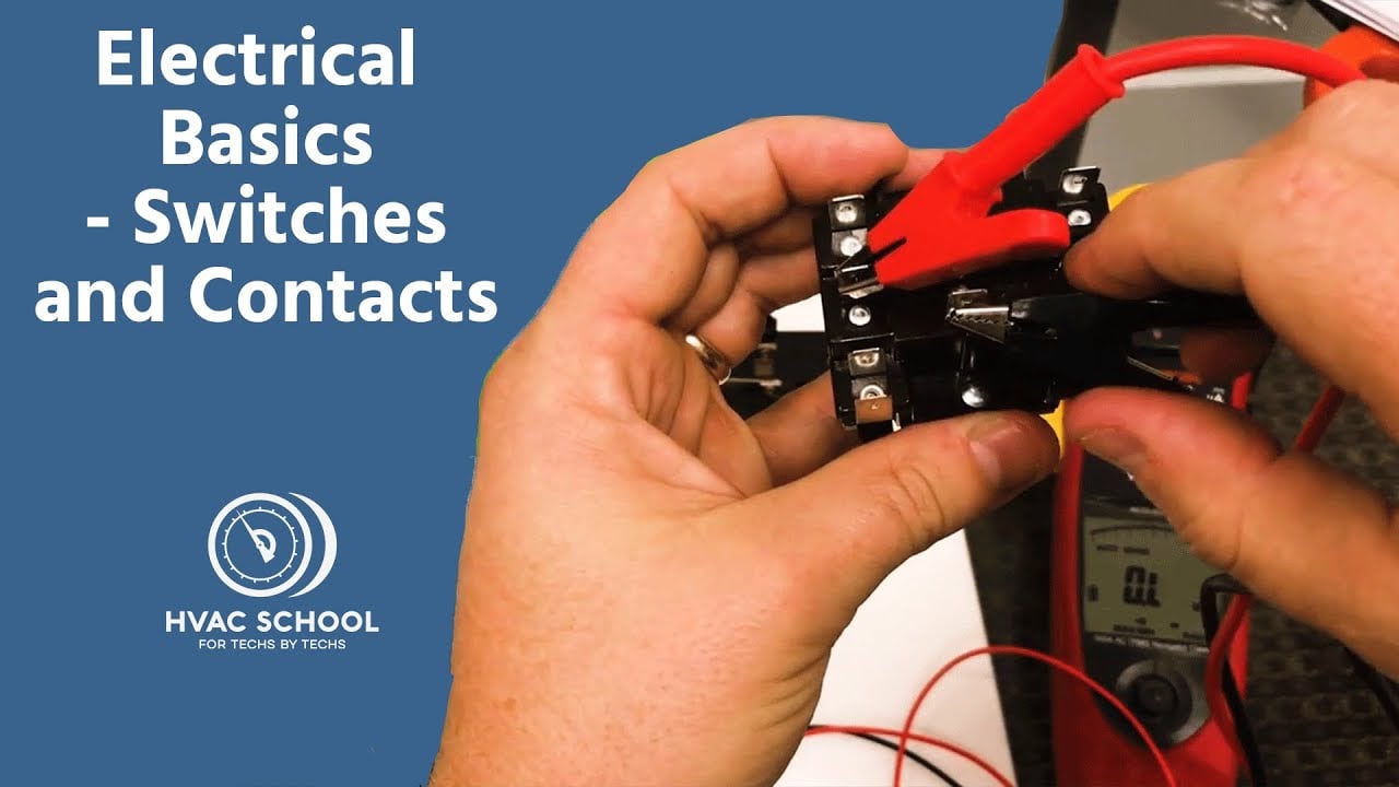
Electrical Basics – Switches and Contacts by HVAC School. General contact behavior; the exact selector diagram and machine design govern. Open the video on YouTube.
Gyakran ismételt kérdések
Is every three-position switch a Hand–Off–Auto switch?
No. Three positions describe mechanical states. The contact arrangement and machine logic determine whether the assembly implements the required HOA function.
Should both request paths be open in Off?
That is a common HOA requirement, but the approved functional specification governs. Verify the exact contact table instead of assuming the center position opens every contact.
Does Hand bypass the machine’s safety conditions?
It should not be assumed to do so. Any manual operating mode must preserve the safeguards and permissives required by the machine design and assessment.
Can Hand and Auto share an input common?
Only if the exact controller and circuit documentation permit it. Do not join different supplies or input references based on nominal voltage alone.
What should be checked after replacing the selector?
Confirm the complete order code, contact table, operator action, orientation, terminal mapping, labels, and actual machine response in each mode and transition.



