

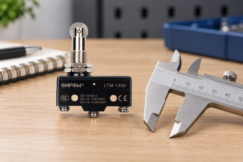
Subminiature and miniature micro switches describe families of compact snap-action components, but the names do not establish a universal body size, current rating, force, or life. Compare the exact dimensions and declared electrical and mechanical characteristics before choosing between them. A smaller body can solve a packaging problem while making terminal access, actuator alignment, mounting support, or contamination control more demanding. The correct choice is the component that fits the complete mechanism and circuit over their expected tolerances. Do not assume a subminiature version is electrically interchangeable with a larger switch simply because both have three terminals.
Treat size names as a starting point
Manufacturers organize product families differently. Miniature and subminiature labels help navigate a catalogue, but they cannot replace an outline drawing. Measure the complete installed envelope: body, actuator, terminal projection, connector or solder joint, wire bend, mounting hardware, and maintenance clearance.
A small body with a long lever may occupy more usable space than a larger pin-plunger unit. A compact PCB switch may also need a board keep-out area and support structure. Compare the assembly rather than just the plastic housing width. The mechanism’s motion path can be the real constraint even when there is enough static space for the body.
For the basic operating principle, see how a micro switch works. For the larger installation checklist, use industrial micro switch selection. This comparison focuses on packaging and interchangeability rather than a universal ranking of switch sizes.
Compare the installed envelope in a common drawing
Place candidate outline drawings in the same coordinate system, using the actual mounting reference. Show the target at its initial contact, operating position, maximum approach, and release position. Add the wire route and nearby structures. This makes interference visible before a production bracket is made.
| Comparison item | What to compare between candidates | Why body size alone is insufficient |
|---|---|---|
| Static envelope | Body, actuator, terminals, hardware | Terminals and levers may dominate space |
| Moving envelope | Target path and actuator travel | A small switch may need more clearance around its actuator |
| Felszerelés | Hole spacing, fasteners, supported faces | A close size match may still require a different bracket |
| Electrical interface | Load category, voltage, current, minimum load | Size does not establish contact suitability |
| Service access | Tool approach and conductor removal | A compact assembly can be difficult to maintain |
| Környezet | Sealing and terminal protection | A small unsealed body is not protected by being hidden |
Use actual product data for each entry. Do not fill a comparison table with generic ampere ratings assigned to miniature or subminiature categories.
Check force and travel independently of the body
A smaller body does not necessarily mean lower operating force. Actuator length, spring design, contact arrangement, and measurement method affect the declared values. Compare operating force at the specified contact point, release force, and any force requirement associated with further travel.
The target must cross the operating point at the least favorable tolerance condition and allow release after withdrawal. At the other extreme, it must avoid exceeding permissible travel or imposing an unacceptable load. Moving a bracket until the switch clicks once is not a tolerance analysis.
Lever options need particular care. A long lever can reduce the force applied at its end while changing required target movement and effective geometry. It can also create clearance and alignment issues. Read micro switch roller and cam selection when comparing lever or roller interfaces.
Electrical capacity is a separate specification
Two switches with the same SPDT description may have different ratings for resistive loads, electromagnetic loads, AC, DC, or small electronic inputs. Record the actual operational rating for the application, not only a prominent current number in a listing. The same nominal voltage can still involve different switching stresses.
Contact materials and minimum switching conditions matter when a compact switch is used with a low-current input. A power-rated contact is not automatically the best choice for a very small signal. Ask for the declared low-level capability and the expected electrical life under the intended load.
The IEC 60947-5-1 publication information provides the standards context for electromechanical control circuit devices. It does not equate body categories with ratings or certify a candidate merely because its catalogue uses a familiar size name.
Terminations can decide which package is practical
Compact switches are offered with different terminal forms, such as solder, PCB, quick-connect, or other terminations. These forms need their own installation methods and clearances. A part selected by body dimensions can fail the assembly review when the cable cannot bend safely or the terminal cannot be reached with the intended tool.
For a PCB component, compare the pin layout, board support, soldering instructions, and the mechanical load path. The board may need additional support so that actuation force does not stress solder joints. For a bracket-mounted component, confirm that conductor loads do not move the switch or loosen a terminal.
Do not bend terminals into a different footprint unless the manufacturer’s instructions explicitly permit the method. The change can introduce stress, clearance problems, and inconsistent assembly. An adapter should be designed and verified as part of the installation rather than improvised to make an almost-fitting replacement work.
Consider contamination and enclosure strategy
A compact mechanism may be installed where dust, oil, moisture, or process debris can reach the actuator. Body size does not establish ingress protection, chemical compatibility, or terminal sealing. Review the specified environmental conditions and the protection of the complete installation.
An enclosing cover can protect the switch from some exposure but can also trap contaminants or prevent inspection. A tight space may make cleaning and replacement difficult. Look at the route by which contamination arrives, not only whether the component is behind a panel.
The waterproof micro switch guide explains why sealing must be assessed at the body, actuator, cable or terminals, and mounting interface. A compact catalogue label cannot substitute for those checks.
Review mounting and structural support
Mounting-hole spacing, fastener size, clamping surfaces, and the actuator’s reference position all affect interchangeability. A replacement may fit the same cavity while changing the contact point enough to alter the machine’s sequence. Keep the geometry tied to the exact part number and actuator option.
Do not let the switch body absorb loads that should be carried by the machine frame or an external stop. A flexible bracket can consume target movement. A PCB that bends under actuation can change the observed operating point and fatigue its joints. Provide the support required by the installation instructions and the mechanism’s load path.
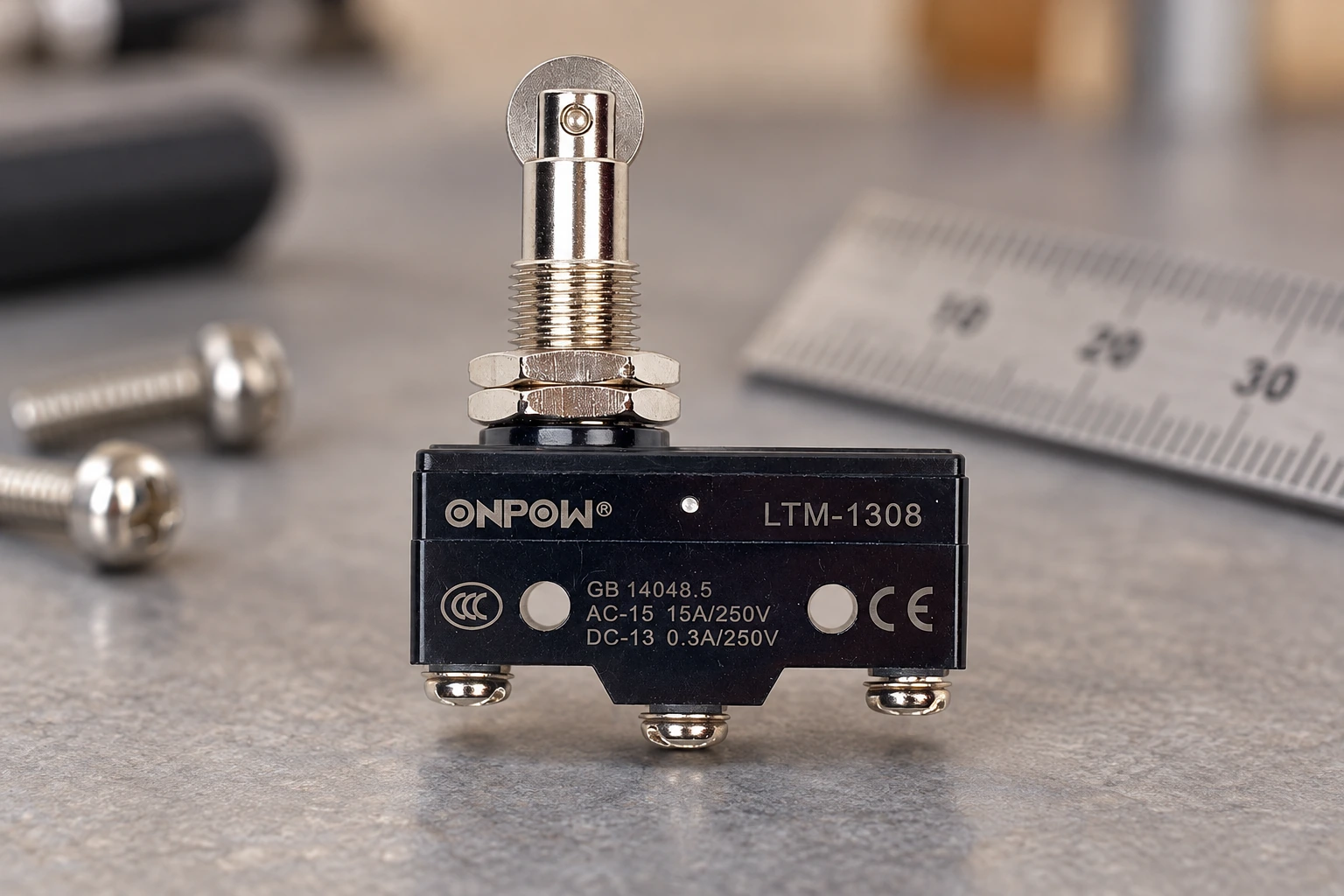
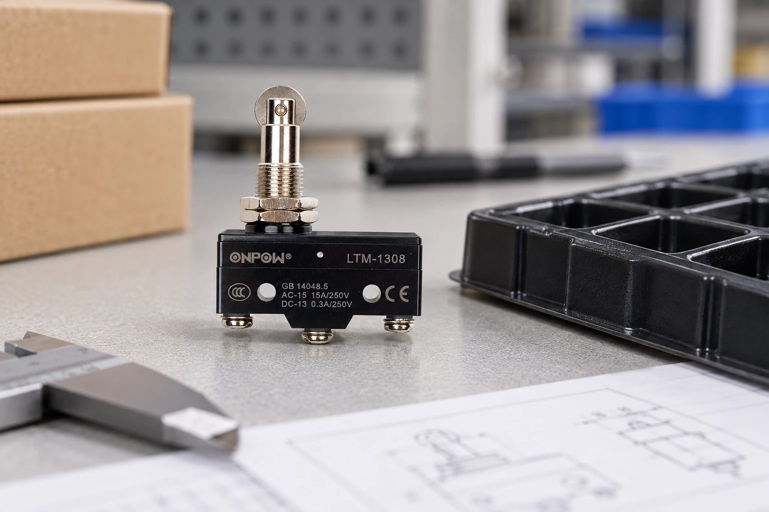
The photographs in this article use an ONPOW LTM-1308 mechanical switch as a known physical reference. They do not claim that ONPOW offers every miniature or subminiature package discussed, or classify that model by an unverified size convention. Ask for available product drawings and evaluate the actual candidates.
Qualify a substitution in the intended assembly
A meaningful comparison test uses the real bracket, target, termination, cable route, input or load, and expected environment. First verify the mechanical envelope and isolated contact behavior under the approved inspection procedure. Then confirm the complete application response through the authorized commissioning plan.
Installed machinery presents stored-energy and electrical hazards. Qualified personnel must follow the applicable procedures; for United States workplaces, relevant requirements include 29 CFR 1910.147 and 29 CFR 1910.333. A smaller component does not make the work safe by reducing its supply voltage or physical size.
Compare approach and release at the relevant tolerance extremes, inspect support after the planned test, and verify the controller’s state. Record differences from the previous part. If a bracket, cable, or circuit changes, treat those as installation changes rather than claiming a drop-in replacement.
Build a purchasing comparison that can be reviewed
Give the supplier the available envelope, mounting references, actuator target path, force budget, electrical load, environmental conditions, and desired service life. Include the actual drawing of the current assembly. Ask which package families meet those requirements and what changes each candidate would require.
Keep declared values separate from missing information. Mark unavailable ratings or travel data as awaiting confirmation instead of inferring them from another model. The final selection record should include the exact suffix, approved drawing revision, required assembly method, and inspection criteria.
A useful outcome is a documented reason for the selected package: adequate fit, compatible force and travel, appropriate electrical performance, protected environment, and maintainable installation. Merely choosing the smallest listed part is not an engineering requirement and can create avoidable service problems.
Educational video
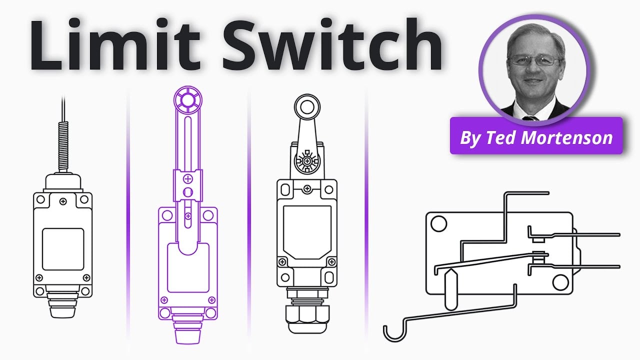
Limit Switch Explained | Working Principles by RealPars. General educational background. Use the selected product drawing and the machine design for the actual circuit and installation. Watch on YouTube.
Frequently asked questions
Is subminiature a fixed maximum dimension?
Do not assume a universal dimension from the name. Compare the manufacturer’s family definitions and the exact outline drawing of each candidate.
Can a smaller switch carry the same load as a larger one?
Only if its declared ratings support that load and operating conditions. Body size alone does not establish electrical capacity or life.
Are three-terminal miniature switches interchangeable?
No. Contact arrangement, terminal map, mounting, actuator geometry, force, travel, ratings, and environment all need confirmation.
Does a smaller housing require less actuation force?
Not necessarily. Force depends on the internal mechanism, actuator option, and specified contact point. Use the actual mechanical data.
What should be checked before replacing a PCB switch?
Verify footprint, terminal form, board support, soldering instructions, actuator alignment, electrical suitability, and the complete assembly response.
Customization
ONPOW undertakes a variety of custom needs for push-button development. Confirm whether packaging, marking or documentation OEM/ODM applies to Subminiature vs Miniature Micro Switches in the quotation.
Minimum order quantity, lead time and trade terms are not published here; confirm them with sales at sales@onpow.com.



