

AC-15 and DC-13 utilization categories describe specified control-circuit switching duties, so a push button must be selected using the category, operational voltage and corresponding operational current together. AC-15 concerns AC electromagnetic control loads, while DC-13 concerns DC electromagnetic control loads. Neither marking is a universal current rating for every load. A thermal current value, a resistive-load rating and a control-duty rating answer different questions. Before ordering an operator or contact block, identify the actual coil, supply and switching sequence, then obtain the exact assembly’s verified rating for that duty.
Read a control rating as a complete statement
A catalogue may show several current values beside one switch. Some describe a thermal condition, while others describe switching at a stated voltage and utilization category. Copying the largest number into a purchase specification loses the conditions that make the number meaningful. Ask which value applies to the intended opening and closing duty.
The IEC 60947-5-1 publication page identifies the standard’s scope as electromechanical control-circuit devices and switching elements. The full applicable standard and manufacturer documentation are needed for detailed test conditions. A public scope page does not establish that a particular ONPOW assembly has been tested or certified to every requirement.
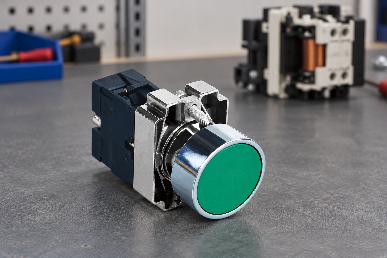
Use the ONPOW HBY5-11 product page as a real control-operator starting point. Request the exact contact block’s rating table and order code. Do not infer the rating from actuator colour, mounting diameter or a photograph of a marking on another product variant.
Identify the electromagnetic load
For a relay, contactor or solenoid, obtain the coil supply type and its specified operating characteristics. AC and DC coils require different assessment, and two coils sharing a nominal voltage can still impose different switching duties. Identify the manufacturer and coil code in the enquiry so that the load can be checked rather than approximated from its physical size.
Record whether the contact closes the coil circuit, opens it, or performs both operations during normal use. Include switching frequency and expected operating life. A control that operates a few times during commissioning presents a different service pattern from a frequently used production command, even when both connect to the same nominal coil voltage.
Document any parallel indication, suppression device or electronic module. These features can influence current paths and transient behaviour. Do not treat a circuit drawing that shows only an ideal coil symbol as a complete description when additional components are fitted in the actual machine.
Distinguish utilization category from other markings
The qualitative comparison below helps organise an enquiry. Numerical ratings must come from the exact manufacturer’s table for the assembly and voltage concerned; no conversion factor is implied by the table.
| Information | What it helps establish | What it does not establish alone |
|---|---|---|
| AC-15 rating at stated voltage | Suitability within a specified AC control duty | Suitability for an arbitrary motor or DC load |
| DC-13 rating at stated voltage | Suitability within a specified DC control duty | The same current capability at every DC voltage |
| Thermal current information | Carrying performance under stated conditions | Equivalent making and breaking performance |
| Resistive-load rating | A specified resistive switching duty | Equivalent electromagnetic coil switching duty |
| Minimum-load information | Low-level switching applicability | Maximum control-load capability |
| Mechanical life information | Operation under stated mechanical conditions | Electrical endurance under the actual load |
Why an AC rating cannot simply be copied to DC
The interruption conditions of AC and DC circuits differ. A rating demonstrated for one supply and duty does not automatically establish the same current capability for another. Procurement should request the DC rating directly when the load is DC, even if the switch has a much larger AC number printed prominently in a catalogue.
Do not create an informal conversion rule based on voltage ratio. Contact separation, arc behaviour and the approved test duty are not captured by a simple arithmetic rescaling. If the supplier’s table does not include the intended condition, ask for an engineering assessment or choose a suitable interface architecture.
The same caution applies when changing a machine from an AC coil to a DC coil. The operator may remain physically compatible while the electrical duty changes. Treat the supply conversion as a design change and review contact ratings, suppression, indication and control response together.
Keep control duty separate from direct motor switching
A push button can command a contactor without carrying the motor’s full load current. In that arrangement, its contacts are assessed for the control circuit, while the contactor is assessed for the motor circuit. The distinction must be clear on the schematic and in the bill of materials.
A push button with a reassuring current number should not be assumed suitable for directly interrupting a motor. The guide to direct-load switching versus a contactor explains the broader architecture question. Select the complete arrangement using the actual load and required protective measures.
Likewise, a relay coil circuit does not become a negligible load simply because the machine calls it a “signal.” Find out what the contact actually switches. A controller input, an electronic interface and an electromagnetic coil can all appear as command destinations while requiring different contact information.

Account for suppression without assuming equivalence
A suppression component can change a coil circuit’s transient behaviour and release response. Record the exact arrangement, including whether it is built into the coil assembly or added externally. Ask the load manufacturer and switch supplier to assess the actual circuit. Do not assume that adding a component automatically raises the contact’s published utilization-category rating.
Changing release behaviour can matter to the process even when contact stress is reduced. Assess the required response at the machine level and validate it under the approved procedure. The separate article on DC relay flyback diodes covers that component-selection problem; it is not a replacement for a verified contact rating.
Where safety-related control is involved, use the applicable design and validation process. An ordinary utilization-category marking does not by itself demonstrate a safety function, diagnostic coverage or the required system performance. Keep component duty and system safety evidence clearly identified.
Build a configuration-specific rating checklist
Create one line for each switched load. Include load identity, supply, operational voltage, current characteristics, contact function, switching frequency, suppression and intended life. Then add the proposed contact block’s matching table entry and any manufacturer qualification notes. A blank matching entry is a question to resolve before release.
Confirm that ratings apply to the ordered combination of operator, adapter and contact blocks where the manufacturer’s documentation makes that distinction. The push button contact block guide explains why a mechanically compatible block should not automatically be treated as electrically equivalent.
Check terminal and installation requirements separately. A correct switching rating does not cancel conductor-size limits, tightening requirements, ambient conditions or enclosure considerations. Use the complete installation instructions and preserve them with the approved bill of materials.
Validate function under controlled conditions
Start with a drawing review and an isolated assembly check. Confirm that the intended contact pair changes state correctly and that lamp terminals are not mistaken for switch terminals. Then perform the authorised functional test with suitable protection and competent personnel. A successful initial operation is evidence of that test, not proof of the complete endurance rating.
For installed equipment, follow the site’s energy-control procedure before service or rewiring. OSHA 1910.147 provides a US reference for hazardous-energy control. Pressing a stop command is not a substitute for isolation and verification where the procedure requires them.
If a contact fails during testing, preserve the sample and record the circuit as built. Include supply measurements, load code, suppression arrangement, operating sequence and observed symptom. Replacing the switch immediately with a higher-numbered device can hide the original mismatch without establishing a sound selection basis.
Write a useful RFQ and replacement rule
An effective request states: “This contact operates the identified coil at the stated supply under this switching sequence; please confirm the applicable category, operational voltage, current and endurance conditions for the proposed assembly.” Attach the coil documentation and schematic. This is more useful than asking for a generic high-current push button.
For replacement stock, preserve the approved contact block code and rating conditions. A later substitute should be reviewed against the complete duty, not just panel fit or terminal count. Include any restrictions in the maintenance record so that the original selection evidence survives staff changes.
Ask ONPOW to provide the exact assembly information and identify any missing load details. If the required duty is outside the available table, consider a suitable intermediary device or another configuration after engineering review. Do not invent a rating to keep a preferred operator appearance.
Frequently asked questions
Is AC-15 the same as a resistive current rating?
No. It describes a specified control duty. Read it with the operational voltage, operational current and applicable conditions.
Can an AC current rating be used unchanged for a DC coil?
Do not assume that. Obtain the corresponding DC duty rating or a written assessment for the exact circuit.
Does a suppression device make any contact suitable?
No. It changes aspects of the circuit and may affect release response, but it does not automatically create a new verified switch rating.
What information matters most when asking for a contact block?
Provide the load code, supply, switching sequence, frequency, suppression arrangement and intended life, together with the required contact configuration and installation constraints.
Further learning
An educational lecture on contactors and the relationship between control and power circuits. Use the exact switch rating table for AC-15 or DC-13 selection.



