

An industrial push button that sticks after installation needs a mechanical investigation as well as an electrical check. First establish whether the operator physically fails to return, the contacts remain in the wrong state, or the control system continues a command after the button has returned normally. These are different faults. Stop using a suspect control and follow the equipment’s safe isolation procedure before inspection. Do not spray lubricant into the assembly or increase operating force as a routine remedy. The correct repair depends on the exact mechanism, installation and environment.
Define what “sticking” means on this machine
Operators often use the same word for several symptoms: a button stays depressed, movement becomes rough, a command persists, or the front light remains on. Ask the person who observed the issue to describe the physical movement and machine response separately. Record when the problem first appeared and whether it occurs every time or only after cleaning, warming up or closing the enclosure door.
Confirm the intended action from the approved device information. A maintained push button is expected to remain in a selected state until reset by its mechanism. A momentary operator should return as specified. Confusing these actions can lead to replacing a healthy switch or, more seriously, treating an unintended maintained command as acceptable behavior.
The existing bad push button symptoms guide provides a broad starting point. This article focuses on repeated mechanical sticking in an installed industrial panel, especially when a replacement initially works and the same symptom returns later.
Record the conditions before disturbing the installation
Photograph the front and rear assembly, mounting features and adjacent wiring. Note the product code, holder and block combination, panel material and installation drawing. Record whether the enclosure door is open or closed when the symptom occurs. Door movement can change wire tension or bring a rear assembly into contact with equipment mounted behind it.
Ask about recent changes. A new panel coating, replacement gasket, additional legend plate, revised cleaning agent or relocated cable bundle can alter the installed conditions without changing the switch part number. A repair record that says only “button replaced” loses the information needed to identify these repeated causes.
Do not reproduce the fault by repeatedly operating hazardous machinery. Competent personnel should select a safe inspection and testing method consistent with the site’s risk assessment and energy-control procedure. A photograph or video of normal production behavior can be useful if already available, but observation must never take priority over controlling the hazard.
Separate operator movement, contact state and machine logic
Treat the control as a chain: the user’s force moves the operator, the mounting system transfers movement, the contact mechanism changes state, and the control system interprets the input. Investigate the chain in that order while maintaining safe working conditions. A fault in one section should not be assumed from a symptom seen at another.
If the operator returns normally but the command persists, investigate contact behavior and control logic rather than labeling the problem mechanical sticking. If a contact changes correctly but the machine input does not, the wiring or input circuit needs attention. If the machine input changes correctly but the action continues, the relevant control logic and function must be reviewed.
| Observation | Possible investigation area | Evidence to obtain |
|---|---|---|
| Head physically remains depressed | Operator, contamination or mounting stress | Intended action and mechanical condition |
| Movement changes when door position changes | Rear clearance or wire loading | Door sweep and cable route inspection |
| Movement is normal but contact state is wrong | Block, actuator transfer or contact damage | Documented state table and suitable isolated check |
| Contact is correct but input remains active | Wiring, leakage or input circuit | Approved circuit drawing and controlled measurements |
| Input is correct but command persists | Logic or intended maintained behavior | Program/function review by responsible personnel |
| Failure returns after cleaning | Material compatibility or contamination | Cleaning procedure and manufacturer guidance |
This is a diagnostic framework, not proof that any listed cause exists in a particular installation. Use observations to choose the next safe check rather than replacing parts in the order shown.
Inspect installation stress without inventing a torque value
Mounting hardware must follow the exact device instructions. Excessive force can damage components, while insufficient retention can allow movement. There is no universal nut torque, panel thickness or gasket compression that applies to every push button. Obtain the product’s approved mounting arrangement and compare it with the actual installation.
Check whether the panel opening is distorted, burred or obstructed by coating. Examine whether extra washers, labels or seals have been added outside the approved stack. A panel modification that changes the way the operator sits can affect alignment and movement. Do not enlarge a hole or remove a seal as an informal trial without an approved repair plan.
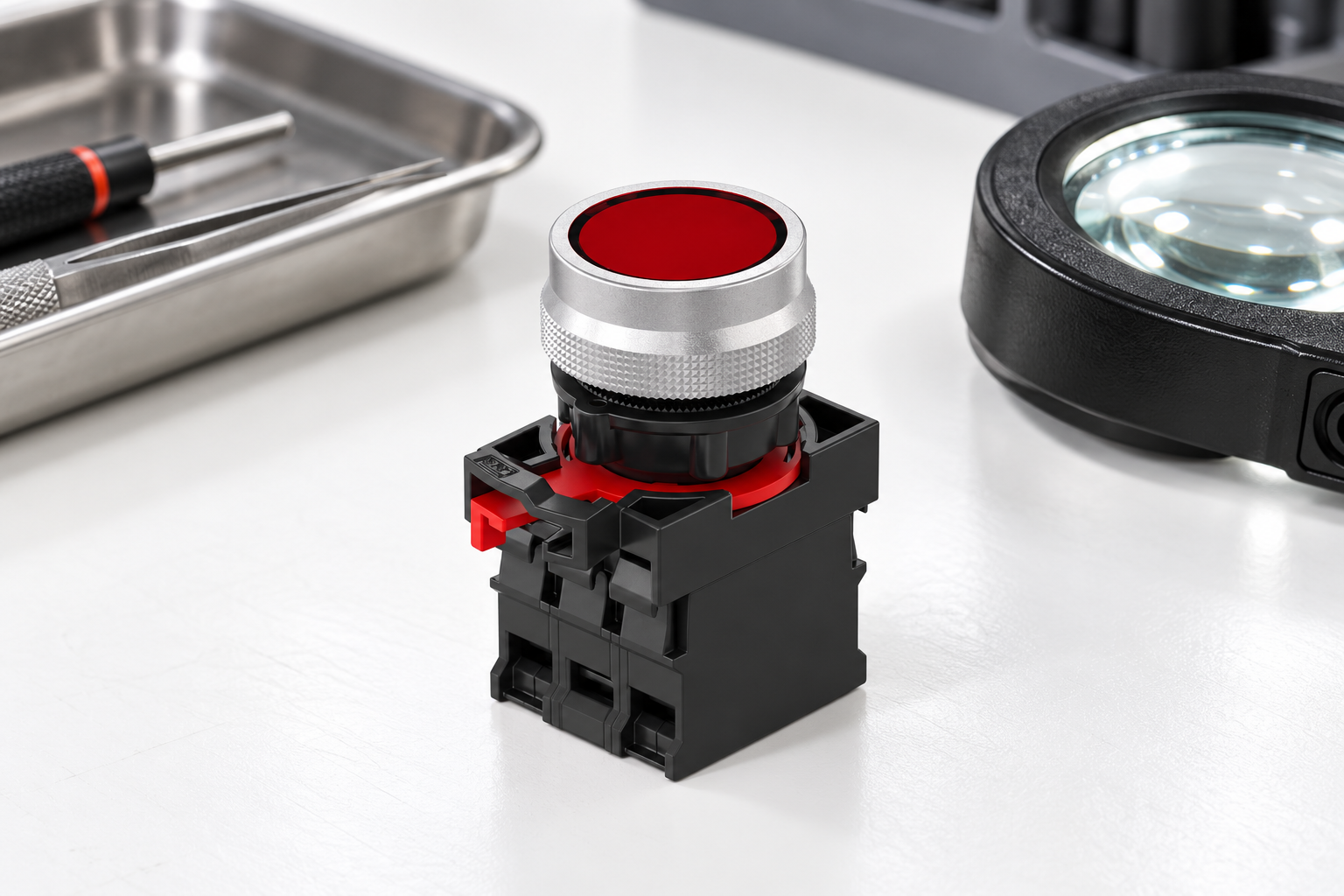
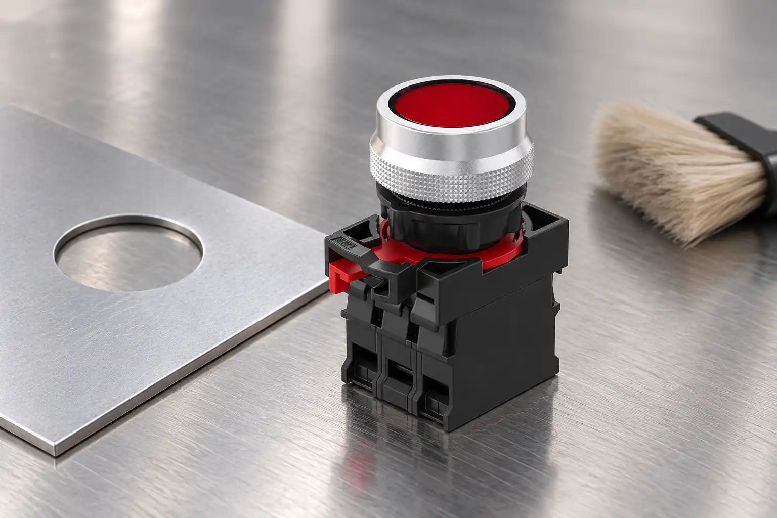
The ONPOW26-11 product illustrates a real operator and rear assembly. The article images are editorial references to that product form; they do not specify installation force or show an approved repair operation. For a complete installation decision, use the panel-mounted push button guide together with the exact drawing.
Examine the rear assembly and wire route
A correctly installed head can still be affected by an incorrect holder, damaged latch or incompatible rear block. Confirm the approved combination of components and permitted block positions. Do not assume that parts from different families are compatible because they connect during a bench trial. Preserve photographs of the installed arrangement before changing it.
Inspect the space behind the assembly. Wire bundles, cable duct lids or a nearby component may press against it when the door closes. The wire route should allow normal door movement without pulling on terminals or twisting the switch. Service work on neighboring equipment must not leave a load on the control’s rear components.
When a rear block is suspected, follow the replacement evidence process in contact block selection. Any permitted separation of components must follow the manufacturer’s instructions. Do not pry at a latch or operate an unsupported mechanism simply because it appears accessible.
Treat contamination and cleaning as engineering conditions
Dust, sticky process residue and liquid contamination can change the feel of an operator. Their presence also raises questions about the suitability of the device and enclosure for the application. A stated front protection rating does not automatically describe the rear assembly or establish resistance to a particular solvent, detergent or cleaning method.
Obtain the approved cleaning guidance for the exact assembled product. Do not extrapolate from “stainless steel” to the behavior of seals, plastics, markings or internal mechanisms. Avoid recommending a lubricant or cleaner without documented compatibility. A material that removes visible residue may also affect a seal or leave a film that creates a later problem.
Record the cleaning agent, dilution, application method and any recent changes. Where the issue appears after washdown, review the finished equipment’s cleaning procedure and protection design rather than assuming that the switch alone is responsible. Replace damaged parts through an approved process and correct the exposure that caused the damage before returning to service.
Decide between adjustment, component replacement and redesign
A repair should address the identified cause. Correct an installation error according to approved instructions; replace damaged components with an approved combination; review the equipment design when the environment, clearance or operating duty is unsuitable. Repeatedly fitting the same part without investigating recurrence is not a complete maintenance strategy.
Preserve the distinction between observation and explanation. “The head did not return on three inspected operations” is an observation. “The spring failed because of chemical exposure” is a causal conclusion requiring evidence. Keep suspected causes identified as hypotheses until inspection, documentation or testing supports them.
For safety-related controls, a successful bench return test is not sufficient to restore the machine. The equipment’s responsible personnel must establish the required functional checks and validation. Do not bypass the control, hold contacts in a convenient state or modify logic to keep production running while the cause remains unresolved.
Verify that the repair survives the installed conditions
Acceptance should include the actual assembled condition, relevant door positions and the normal cable route. Confirm the intended mechanical action and contact sequence using the approved method. Check that adjacent maintenance access has not been blocked and that inspection labels and records remain readable.
Where contamination, cleaning or temperature was involved, define a controlled follow-up that reflects the relevant service conditions. Do not invent an arbitrary number of operations as a universal pass criterion. The required checks and duration must come from the application, manufacturer information and the site’s maintenance plan.
Close the record with the observed fault, confirmed cause where known, parts changed and checks completed. If the cause remains uncertain, record that limitation and retain the evidence. Ask ONPOW for exact product guidance using the full order code, installation photographs and a clear description of the physical and electrical symptoms.
Frequently asked questions
Should I lubricate a sticking push button?
Only when the manufacturer explicitly specifies an appropriate product and method for that assembly. Unapproved lubricant can affect materials or collect contamination. Investigate the cause and use the documented maintenance procedure.
Can tight wiring make a button stick?
Wire loading or restricted rear clearance can affect an installed assembly and should be checked. Their presence does not prove they caused the fault. Inspect the complete mounting arrangement and compare it with the approved design.
Why does a replacement button develop the same problem?
The underlying installation, environment or application duty may remain unchanged. Preserve the failed parts and investigate recurrence, including mounting, contamination, wiring forces and the approved component combination.
Is a light that stays on proof of a stuck contact?
No. Indication, contact state, control input and machine action can be separate circuits or functions. Identify which part of the chain is behaving incorrectly before selecting a repair.
References and boundaries
HSE safe electrical maintenance guidance and HSE work equipment maintenance guidance provide the general maintenance and safe-working context. Exact disassembly, cleaning compatibility, mounting requirements and acceptance criteria must come from the equipment and component manufacturers.
Further learning
University background on electrical measurement and instruments, supporting the separation of physical operator movement, contact state and machine input. Use the equipment-approved safe troubleshooting procedure.

NPTEL: Electrical Measurement and Electronic Instruments — NPTEL IIT Kharagpur



