A relay socket retaining clip should be selected as part of a documented relay, socket and accessory combination. Its job is mechanical retention within that assembly; it does not prove electrical contact quality, environmental suitability or immunity to equipment vibration. Begin with the exact component codes and the equipment’s operating conditions, then verify the approved accessory and maintenance procedure. Do not fit an improvised strap or a visually similar clip and treat the result as qualified. This guide explains the retention decision separately from relay pin identification and socket wiring.
Identify what is moving before adding retention
An intermittent control circuit in vibrating equipment can have several causes. The relay may move in its socket, the socket may move on its mounting, a conductor may be loose, or another part of the control circuit may be responsible. A retaining clip addresses only a specific mechanical interface and should not be used to conceal an unidentified fault.
Record the symptom, operating conditions and observed location of movement. Note whether the issue appears during machine operation, transport or maintenance. Preserve photographs of the complete installation, including the relay, socket, mounting, wiring and any existing accessory. Do not investigate by manipulating an energized assembly in operating equipment.
For the broader fault analysis, see electromechanical relay failure modes. This article concentrates on preventing unintended relay displacement while preserving approved installation and service access. It does not assign a vibration rating to a pictured product.
Match the complete assembly by exact code
Identify the relay, socket and proposed retainer separately. A relay family name or pin count may not identify the required accessory. Body shape, height, release features and socket construction can differ between versions. Obtain the manufacturer’s approved combinations and any installation restrictions.
Confirm whether the retainer is supplied with the socket, ordered separately or included only in a particular configuration. Purchasing a relay and socket from the same manufacturer does not automatically establish that every accessory in that catalogue fits the pair. Keep the actual order codes and revisions together in the equipment record.
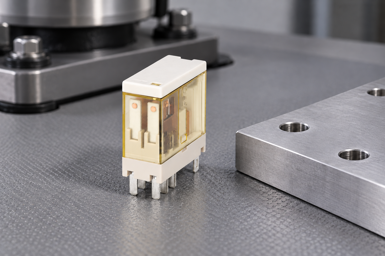
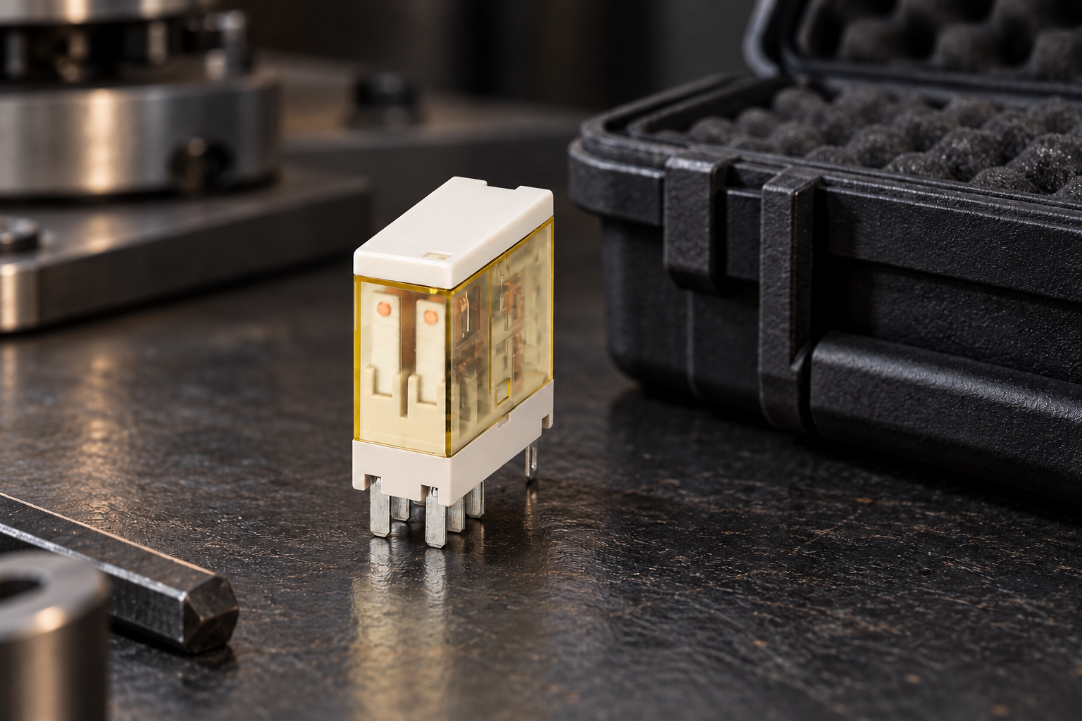
The ORJ2SL relay product page provides a real ONPOW relay reference. The editorial photographs deliberately show the standalone relay rather than an invented socket or clip. Printed markings are deliberately omitted from these illustrations; use the exact product documentation for identification, ratings and terminal diagrams. The photographs establish the product form being discussed, not approval of a retention accessory or an installation vibration limit.
Define the service environment without borrowing a rating
Describe where the assembly will operate and what motion it may encounter. Equipment operation and transport can impose different conditions. A component’s stated test result applies within its documented configuration and conditions; it should not be converted into a general claim that the finished cabinet tolerates every vibration environment.
Ask the supplier which assembly and test conditions support any available mechanical rating. Record whether the result covers the relay alone, the relay in a particular socket, the accessory and mounting arrangement, or another configuration. Keep axes, mounting orientation and other conditions attached to the statement where supplied.
If the equipment requirement is not covered by existing evidence, develop an appropriate qualification plan with responsible engineering personnel. Do not choose an arbitrary test severity or duration and label it an industry-wide pass criterion. The plan should address the actual application and applicable equipment requirements.
Distinguish the interfaces in the mounting chain
The assembly has several mechanical interfaces. Retaining the relay in its socket does not ensure that the socket is correctly mounted, that a rail is adequately supported or that the enclosure structure is suitable. Inspect the complete chain and identify which part each accessory is intended to secure.
Wire support belongs in the same review. A tightly routed conductor can load the socket terminal or influence the assembly when a cabinet door moves. A clip cannot correct an unsuitable wire route. Maintain separation between retention of the relay body and support of the connected wiring.
| Interface | Evidence to obtain | What a relay clip cannot establish |
|---|---|---|
| Relay to socket | Approved fit and insertion arrangement | Correct pin mapping or electrical rating |
| Retainer to assembly | Exact compatible accessory and installation method | Universal cross-family compatibility |
| Socket to mounting | Approved mounting and orientation | Strength of the cabinet structure |
| Wiring to terminals | Permitted conductor and assembly instructions | Adequate strain relief elsewhere |
| Assembly to environment | Relevant test evidence or qualification plan | Immunity to every vibration condition |
| Service access | Safe removal and replacement procedure | Suitability of an improvised restraint |
Use the table to find missing evidence before release. The number of interfaces is a reason to document the assembly, not to add multiple unapproved restraints until it feels secure.
Install only according to the accessory instructions
Obtain the correct installation sequence and identify the intended engagement points. A clip can appear fitted while not being fully engaged, or it can be installed in a way that interferes with another feature. Use the manufacturer’s inspection method rather than judging the result only from the front.
Do not bend, trim or reshape an accessory to fit an assembly for which it was not intended. Do not substitute cable ties, adhesive or packing material as a permanent retention method unless the equipment design explicitly specifies and qualifies that arrangement. An improvised restraint can also make safe replacement more difficult.
Check that the accessory does not obstruct markings, test controls, indication, terminals or other required features. Verify the actual configured assembly in its installed location. A successful fit on a bench does not establish access once cable ducts and adjacent equipment are present.
Keep electrical verification separate from retention
A relay that is held firmly can still have an incorrect coil voltage, unsuitable contact duty, a wiring error or a degraded connection. Verify the electrical requirements independently. Refer to the plug-in relay socket guide for socket identity and circuit mapping rather than inferring the wiring from the retainer’s appearance.
Use suitable approved methods to inspect and test the circuit under safe conditions. Do not make live adjustments to diagnose a mechanical retention problem. Any energized testing must be planned and controlled by competent personnel under the equipment’s procedure.
Keep coil suppression, indication and polarity information with the assembly record where relevant. A socket or accessory substitution can change the actual configuration even when the relay body remains the same. Check the exact documentation rather than assuming that a mechanical replacement has no electrical consequences.
Plan representative qualification checks
Use the real relay, socket, accessory, mounting and wire arrangement in the qualification configuration. Record the component codes and how the assembly was installed. If a test fixture differs from the equipment, explain the difference and why the result remains relevant.
Define acceptance criteria before testing. They may include retention, visible condition, applicable electrical behavior and ability to service the assembly, as established by the responsible engineering process. Do not interpret a relay remaining physically seated as complete proof that every connection or contact function stayed acceptable.
Inspect the assembly after the relevant exposure and record any change. Preserve observations such as movement, wear, damaged latches or altered wire routing. A passing result should identify the tested configuration and conditions rather than becoming a permanent blanket approval of a product family.
Make maintenance possible without defeating retention
The equipment should provide a safe way to identify and remove the correct relay. A retainer that cannot be accessed without disturbing adjacent energized circuits creates a service planning problem. Resolve that access through the equipment design and maintenance procedure rather than leaving the accessory off.
Document the removal and refitting sequence, including any accessory inspection or replacement requirements from the manufacturer. Train service personnel to verify engagement after a relay change. A maintenance operation can unintentionally remove the benefit of the original retention design if the accessory is not restored correctly.
For component verification, see testing electromechanical relays. Electrical checks and mechanical retention checks answer different questions, so retain both sets of results where the application requires them.
Specify the combination in purchasing and spare parts
An effective inquiry includes the relay and socket codes, proposed accessory, mounting arrangement, available service space and application environment. Ask the supplier to confirm the combination and identify any relevant test evidence. State whether the requirement concerns normal operation, transport or both.
List the approved retainer in the equipment bill of materials rather than treating it as an optional workshop item. Define the spare assembly and any permitted alternatives. A replacement socket that appears electrically similar should trigger a compatibility check for the retainer and mounting system.
Contact ONPOW with the actual installation information when a documented combination is not clear. The useful outcome is an identified assembly with stated limits and a safe maintenance method. A photograph of a clip on a different relay does not provide that evidence.
Frequently asked questions
Does a retaining clip make a relay vibration-proof?
No. It is one part of a documented mechanical assembly. The relevant vibration evidence must cover the actual configuration and conditions, and the finished equipment may require its own qualification.
Can I use any clip with a relay of the same pin count?
No. Pin count does not establish body, socket or accessory compatibility. Use the exact manufacturer’s approved combination and installation instructions.
Can a clip fix intermittent relay contacts?
Not without a confirmed cause. Investigate the relay, socket, mounting, wiring and control circuit. Mechanical retention cannot establish correct electrical ratings or repair a damaged contact system.
Should the retainer be included in the spare-parts list?
Yes, when it is required by the approved assembly. Identify the exact accessory and its service requirements so that replacement work restores the intended configuration.
References and scope
HSE work equipment maintenance guidance supports planned, safe maintenance, and HSE electrical maintenance safety provides the electrical safe-working framework. Exact accessory compatibility, installation instructions and mechanical ratings require the relay and socket manufacturer’s documentation.
Further learning
An educational lecture on contactors and control/power circuit separation. It complements the distinction between mechanical retention and electrical operation; it does not approve a relay/socket/clip combination.