

Ring illumination vs dot illumination is first an HMI choice, not a voltage choice. A ring places a halo around the actuator and works well when the operator should recognize the control location or a broad status cue. A dot presents a concentrated central light area and can suit a focused indicator. Neither style automatically makes a printed legend readable, nor does either style tell you how the exact model is wired.
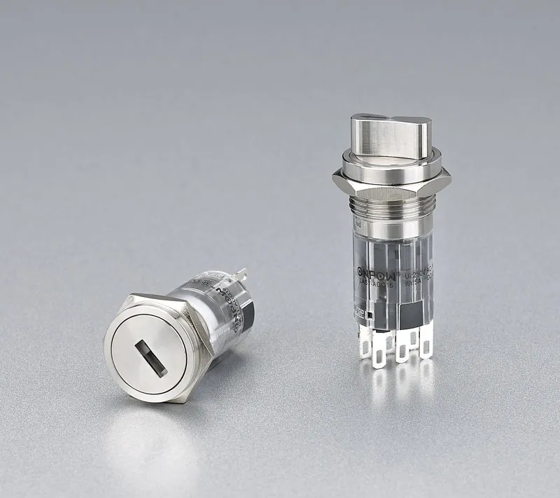
Part 1. Choose the visual job first
Start by defining what an operator should notice. A perimeter halo can make the actuator outline easy to locate and can provide a continuous “present” cue around the button. A central dot gives a smaller, more focused source that can work where the panel already provides a clear label or symbol nearby.
The correct choice is not universal. Ring illumination is often selected for an obvious control boundary; dot illumination is often selected for a more compact visual marker. Ambient light, viewing angle, spacing between controls, colour convention, and the actual optical construction all influence the final result. A sample installed in the intended panel is more reliable than judging the geometry from a catalog image.
Do not use appearance to select an LED supply. The electrical requirement belongs in the model configuration and wiring review. For that separate topic, see the LED supply-voltage selection guide.
Part 2. Compare ring and dot geometry
The terms describe where the visible light is presented on the actuator face. They do not promise a common brightness, uniformity, colour, terminal arrangement, or function across brands and models.
| Decision point | Ring illumination | Dot illumination |
|---|---|---|
| Visual shape | Light around the actuator perimeter | Concentrated central light area |
| Useful visual role | Locate a control or show a broad presence cue | Provide a focused marker or status point |
| Legend relationship | A separate legend may still need its own contrast and placement | A nearby or integrated symbol still needs review |
| Panel-layout concern | Halo needs clear separation from neighboring cues | Small central cue can be missed in high ambient light |
| Electrical assumption | Never infer from the shape | Never infer from the shape |
Use the table as a discussion tool, not as a performance guarantee. Two ring models can have different diffusion, colours, and front-face layouts. Two dot models can use different lenses or symbol arrangements. The product drawing and the sample are the final visual evidence.
Part 3. Check legends, status meaning, and viewing conditions
A lighted actuator and a readable command legend are different interface elements. The light can help an operator find a control or recognize a state, while the legend explains what pressing it does. If the application needs a word, symbol, arrow, or machine-state meaning, review it at normal viewing distance and under the actual ambient lighting.
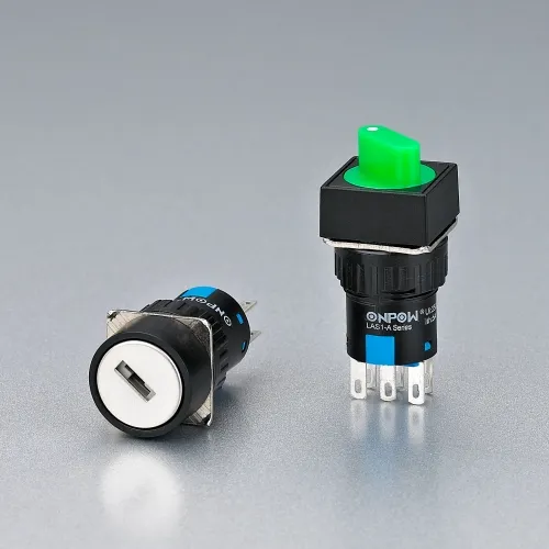
Decide whether the light means “power available,” “ready,” “active,” “fault,” or merely “locate this control.” Then make the meaning consistent across the panel. A bright ring around a stop function and a similar dot on a start function may be visually distinct, but that is not enough by itself to establish an operating convention. The panel legend, colour plan, and machine documentation must agree.
Check these practical points during the layout review:
- Can an operator distinguish neighboring controls without scanning the whole panel?
- Is the legend outside the illuminated area, within a symbol window, or on a separate label?
- Does reflected light from a stainless panel or a protective cover mask the cue?
- Is the control seen straight on, from an angle, or from a standing distance?
- Does the selected colour carry a defined meaning in the machine’s own design?
Part 4. Verify the front interface and terminals
Ring and dot are visual descriptions. They do not define the electrical terminals. An illuminated push button can include contact terminals and additional LED terminals, but the count, markings, polarity, and internal connection depend on the exact model.
Generic wiring explanations commonly refer to COM, NO, NC, LED+, and LED−. Treat that as vocabulary for reading a drawing, not a universal terminal map. Some configurations have different contact sets, different LED circuits, or different terminal constructions. Always compare the switch body markings and the current datasheet with the panel schematic before wiring.
| Item to verify | Dlaczego to ma znaczenie | Evidence to request |
|---|---|---|
| Contact arrangement | Start, stop, or interlock logic needs the intended NO/NC behavior | Exact model code and terminal drawing |
| LED circuit | The LED may be separate from the contacts in a supported configuration | Wiring diagram and rated LED supply |
| Terminal type | Wiring space and assembly method differ | Product drawing and terminal detail |
| Panel interface | Cutout and mounting affect fit and face presentation | Dimensional drawing and panel thickness range |
| Illumination form | Ring, dot, symbol, and colour are configuration choices | Product photo plus current specification |
The LED circuit may be independent of the contact circuit only when the selected model’s diagram shows that arrangement. Do not connect a light source based on a generic article or a picture. Verify the model-specific supply and terminal labels first.
Part 5. Review the whole panel, not one button
A good HMI decision survives the panel layout. Put the proposed ring and dot choices on the actual drawing with labels, pilot lights, selectors, and emergency controls. Check how close visual cues sit to each other, where the operator’s hand approaches, and whether a guard or cover creates shadow.
The mounting diameter can alter the visual balance as well. A 19 mm control may suit a compact interface, while a 22 mm device may provide more front-face presence; neither dimension automatically determines which illumination form is better. For mounting context, consult the 19 mm panel-button guide and the 22 mm panel-button guide.
Before freezing the layout, build a short review with operations, electrical design, and assembly. Operations confirms meaning and visibility. Electrical design checks the circuit. Assembly checks rear clearance, terminals, and access for installation. This avoids choosing a visually attractive actuator that conflicts with a wiring or panel constraint.
Part 6. Use product pages for candidate comparison
Use product pages to shortlist, then request current detail for the exact configuration. The published 19 mm ring-illuminated candidate i 19 mm dot-illuminated candidate provide starting points for comparing form and mounting requirements.
The published 22 mm ring-illuminated candidate lists ring illumination and screw terminals for its named model. That page is not a promise that every ONPOW ring or dot option has identical contacts, protection, LED circuit, or assembly conditions. Ask for the exact drawing before release.
Part 7. Fit boundary and RFQ
This comparison fits a buyer choosing an operator-visible cue and preparing a panel design. It is not a substitute for HMI validation, a wiring diagram, a colour-standard review, or a complete electrical design. Do not choose by illumination shape alone when the legend, ambient light, terminal arrangement, or supply is unknown.
Include these details in an RFQ:
- required ring or dot cue and the intended operator meaning;
- mounting diameter, panel drawing, spacing, material, and thickness;
- legend, symbol, and colour requirement;
- ambient-light condition and normal viewing distance;
- momentary or latching operation, contacts, and terminal type;
- LED supply requirement and request for the exact wiring diagram;
- quantity, delivery target, and documentation requirement.
Use ONPOW’s contact page to request a drawing and terminal confirmation for the selected configuration. That is the point to resolve whether the desired visual geometry, mechanical interface, and electrical circuit belong together in one model.
Najczęściej zadawane pytania
What is ring illumination on a push button?
It is a lighted ring around the actuator area. Its exact optical appearance depends on the model.
What is dot illumination on a push button?
It is a concentrated central light area on the actuator. It can provide a focused panel cue.
Which is easier to see, ring or dot illumination?
Neither is universally easier to see. Compare the actual sample with its legend, panel finish, viewing angle, spacing, and ambient light.
Does ring illumination light the button legend?
Not necessarily. A ring and a legend are different visual elements. Check the actual face layout and symbol treatment.
Do ring and dot push buttons use different wiring?
The illumination shape alone does not define wiring. Verify the exact model’s contact and LED terminal diagram.
How many terminals does an illuminated push button have?
It varies by configuration. Contact terminals and LED terminals can both be present, so request the model-specific drawing.
Can the LED be wired independently of the switch contacts?
It can be in configurations whose wiring diagram shows a separate LED circuit. Confirm the selected model before connection.
What should be included in an illumination RFQ?
State geometry, visual meaning, panel details, legend and colour needs, contacts, LED supply, terminal type, quantity, and drawing request.



