

A lighted toggle switch combines switching contacts with a lamp or LED, but the indicator may be internally connected, share a terminal, or use separate terminals. First determine whether the light should show power available, switch commanded, or load actually energized. Then use the exact lamp voltage and terminal diagram. This guide explains a safe identification and verification process for engineers, panel builders, maintenance teams and buyers. It does not replace the current datasheet, machine risk assessment or locally applicable electrical requirements. The method keeps each decision traceable during purchasing, assembly, commissioning and later service.
Szybka decyzja
Zacznij od funkcji, a nie liczby wyprowadzeń. Opisz wymagane stany stabilne i chwilowe, zidentyfikuj każdy obwód stykowy i lampki, a następnie dopasuj udokumentowane parametry znamionowe do rzeczywistego obciążenia. Podczas identyfikacji zasilanie musi być odłączone. Po instalacji przetestuj zarówno stan elektryczny, jak i reakcję maszyny. Jeśli aplikacja steruje niebezpiecznym ruchem, należy zastosować wymaganą architekturę bezpieczeństwa zamiast traktować przełącznik ogólnego przeznaczenia jako kompletny element bezpieczeństwa.
Kryteria doboru i okablowania
| Decyzja | Co zweryfikować | Powód inżynieryjny |
|---|---|---|
| Indication meaning | Choose power, command or load feedback | A glowing handle can otherwise give a false impression of machine status. |
| Lamp supply | Match AC or DC voltage and polarity where applicable | LED modules may be polarity-sensitive and voltage-specific. |
| Internal connection | Check whether the lamp shares line, load or common | Shared terminals limit the available indication logic. |
| Separate lamp circuit | Use isolated lamp terminals when independent feedback is required | Independent wiring can show a PLC or auxiliary-contact state. |
| Leakage current | Check compatibility with electronic outputs and high-impedance circuits | Small leakage can cause faint glow or unexpected input behavior. |
| Contact load | Treat switch contacts and lamp circuit as separate ratings | The lamp voltage does not establish contact capacity. |
| Heat and space | Allow for illumination module depth and temperature | A lighted body may need more rear clearance than an unlighted version. |
| Test states | Verify lamp and contacts in every lever position and fault state | The visible indication must match the documented meaning. |
Ta tabela ma charakter celowo jakościowy. Numeryczne wartości znamionowe, moment obrotowy, rozmiar przewodów, odległość izolacji, wytrzymałość oraz limity środowiskowe muszą pochodzić z zatwierdzonych dokumentów dla konkretnego urządzenia oraz z kompletnego projektu sprzętu. Wyglądające podobnie przełączniki mogą wykorzystywać różne połączenia wewnętrzne.
Zrozum logikę styków przed okablowaniem
Pole określa, ile niezależnych wspólnych torów stykowych działa razem. Przełączenie (throw) określa, ile styków stałych może wybrać każdy styk wspólny. Termin te nie określają liczby pozycji dźwigni, czy pozycja jest stabilna, czy chwilowa, czy styki nakładają się podczas przełączania, ani jak podłączona jest lampka kontrolna. Szczegóły te wymagają tabeli styków dla każdej pozycji.
Narysuj matrycę z zaciskami w górnym rzędzie i pozycjami siłowników po lewej stronie. Zaznacz tylko połączenia obsługiwane przez bieżący rysunek lub pomiary izolowane. Uwzględnij wyraźny kierunek patrzenia, taki jak “widok zacisków z tyłu z siłownikiem do góry”. Ten prosty zapis zapobiega pomyleniu odwróconych diagramów, obróconych komponentów i numerów gniazd wiązki podczas montażu lub późniejszego serwisu.
Indication meaning
Co zweryfikować: Choose power, command or load feedback. A glowing handle can otherwise give a false impression of machine status. The engineering record should name the exact order code, drawing revision, supply, load and operating state used for the decision. Check the component in its installed orientation because panel thickness, wire routing, adjacent hardware and actuator access can change the result.
Jak to zweryfikować: Porównaj obecny schemat styków producenta z izolowanym testem ciągłości obwodu. Zarejestruj zmierzony stan przed załączeniem, w każdej pozycji stabilnej oraz po zwolnieniu z każdej pozycji chwilowej. Jeśli dokumentacja i pomiar są niezgodne, przerwij pracę i rozwiąż tę niezgodność przed włączeniem zasilania. Nigdy nie wywodź funkcji zacisku na podstawie położenia pinów, koloru metalu ani schematu dla podobnie wyglądającego przełącznika.
Lamp supply
Co zweryfikować: Match AC or DC voltage and polarity where applicable. LED modules may be polarity-sensitive and voltage-specific. The engineering record should name the exact order code, drawing revision, supply, load and operating state used for the decision. Check the component in its installed orientation because panel thickness, wire routing, adjacent hardware and actuator access can change the result.
Jak to zweryfikować: Porównaj obecny schemat styków producenta z izolowanym testem ciągłości obwodu. Zarejestruj zmierzony stan przed załączeniem, w każdej pozycji stabilnej oraz po zwolnieniu z każdej pozycji chwilowej. Jeśli dokumentacja i pomiar są niezgodne, przerwij pracę i rozwiąż tę niezgodność przed włączeniem zasilania. Nigdy nie wywodź funkcji zacisku na podstawie położenia pinów, koloru metalu ani schematu dla podobnie wyglądającego przełącznika.
Internal connection
Co zweryfikować: Check whether the lamp shares line, load or common. Shared terminals limit the available indication logic. The engineering record should name the exact order code, drawing revision, supply, load and operating state used for the decision. Check the component in its installed orientation because panel thickness, wire routing, adjacent hardware and actuator access can change the result.
Jak to zweryfikować: Porównaj obecny schemat styków producenta z izolowanym testem ciągłości obwodu. Zarejestruj zmierzony stan przed załączeniem, w każdej pozycji stabilnej oraz po zwolnieniu z każdej pozycji chwilowej. Jeśli dokumentacja i pomiar są niezgodne, przerwij pracę i rozwiąż tę niezgodność przed włączeniem zasilania. Nigdy nie wywodź funkcji zacisku na podstawie położenia pinów, koloru metalu ani schematu dla podobnie wyglądającego przełącznika.
Separate lamp circuit
Co zweryfikować: Use isolated lamp terminals when independent feedback is required. Independent wiring can show a PLC or auxiliary-contact state. The engineering record should name the exact order code, drawing revision, supply, load and operating state used for the decision. Check the component in its installed orientation because panel thickness, wire routing, adjacent hardware and actuator access can change the result.
Jak to zweryfikować: Porównaj obecny schemat styków producenta z izolowanym testem ciągłości obwodu. Zarejestruj zmierzony stan przed załączeniem, w każdej pozycji stabilnej oraz po zwolnieniu z każdej pozycji chwilowej. Jeśli dokumentacja i pomiar są niezgodne, przerwij pracę i rozwiąż tę niezgodność przed włączeniem zasilania. Nigdy nie wywodź funkcji zacisku na podstawie położenia pinów, koloru metalu ani schematu dla podobnie wyglądającego przełącznika.
Leakage current
Co zweryfikować: Check compatibility with electronic outputs and high-impedance circuits. Small leakage can cause faint glow or unexpected input behavior. The engineering record should name the exact order code, drawing revision, supply, load and operating state used for the decision. Check the component in its installed orientation because panel thickness, wire routing, adjacent hardware and actuator access can change the result.
Jak to zweryfikować: Porównaj obecny schemat styków producenta z izolowanym testem ciągłości obwodu. Zarejestruj zmierzony stan przed załączeniem, w każdej pozycji stabilnej oraz po zwolnieniu z każdej pozycji chwilowej. Jeśli dokumentacja i pomiar są niezgodne, przerwij pracę i rozwiąż tę niezgodność przed włączeniem zasilania. Nigdy nie wywodź funkcji zacisku na podstawie położenia pinów, koloru metalu ani schematu dla podobnie wyglądającego przełącznika.
Contact load
Co zweryfikować: Treat switch contacts and lamp circuit as separate ratings. The lamp voltage does not establish contact capacity. The engineering record should name the exact order code, drawing revision, supply, load and operating state used for the decision. Check the component in its installed orientation because panel thickness, wire routing, adjacent hardware and actuator access can change the result.
Jak to zweryfikować: Porównaj obecny schemat styków producenta z izolowanym testem ciągłości obwodu. Zarejestruj zmierzony stan przed załączeniem, w każdej pozycji stabilnej oraz po zwolnieniu z każdej pozycji chwilowej. Jeśli dokumentacja i pomiar są niezgodne, przerwij pracę i rozwiąż tę niezgodność przed włączeniem zasilania. Nigdy nie wywodź funkcji zacisku na podstawie położenia pinów, koloru metalu ani schematu dla podobnie wyglądającego przełącznika.
Heat and space
Co zweryfikować: Allow for illumination module depth and temperature. A lighted body may need more rear clearance than an unlighted version. The engineering record should name the exact order code, drawing revision, supply, load and operating state used for the decision. Check the component in its installed orientation because panel thickness, wire routing, adjacent hardware and actuator access can change the result.
Jak to zweryfikować: Porównaj obecny schemat styków producenta z izolowanym testem ciągłości obwodu. Zarejestruj zmierzony stan przed załączeniem, w każdej pozycji stabilnej oraz po zwolnieniu z każdej pozycji chwilowej. Jeśli dokumentacja i pomiar są niezgodne, przerwij pracę i rozwiąż tę niezgodność przed włączeniem zasilania. Nigdy nie wywodź funkcji zacisku na podstawie położenia pinów, koloru metalu ani schematu dla podobnie wyglądającego przełącznika.
Test states
Co zweryfikować: Verify lamp and contacts in every lever position and fault state. The visible indication must match the documented meaning. The engineering record should name the exact order code, drawing revision, supply, load and operating state used for the decision. Check the component in its installed orientation because panel thickness, wire routing, adjacent hardware and actuator access can change the result.
Jak to zweryfikować: Porównaj obecny schemat styków producenta z izolowanym testem ciągłości obwodu. Zarejestruj zmierzony stan przed załączeniem, w każdej pozycji stabilnej oraz po zwolnieniu z każdej pozycji chwilowej. Jeśli dokumentacja i pomiar są niezgodne, przerwij pracę i rozwiąż tę niezgodność przed włączeniem zasilania. Nigdy nie wywodź funkcji zacisku na podstawie położenia pinów, koloru metalu ani schematu dla podobnie wyglądającego przełącznika.
Bezpieczna identyfikacja i sekwencja uruchamiania
- Zdefiniuj funkcję. Określ, co powinna sterować każda pozycja siłownika, co dzieje się po zwolnieniu oraz jaki musi być stan normalny po zaniku zasilania.
- Potwierdź tożsamość. Photograph the marking and record the complete order code. Retrieve the matching current drawing rather than a family brochure.
- Isolate energy. Follow the site procedure for disconnecting and controlling hazardous energy. Prove the circuit is de-energized with appropriate equipment before touching conductors.
- Separate the component. Disconnect enough conductors to prevent parallel circuit paths from corrupting continuity measurements. Label every removed conductor.
- Map contacts. Test all terminal pairs in all positions. Repeat the sequence to detect intermittent behavior and note any spring-return action.
- Identify lamps separately. Use the published lamp diagram and voltage. Do not apply an unknown test voltage to an LED or electronic module.
- Review the load. Check normal current, inrush, AC or DC, inductive energy, switching frequency, protection and the consequence of a contact failing open or closed.
- Install mechanically. Confirm cutout, panel thickness, anti-rotation, fasteners, sealing, rear clearance, conductor support and accessible labels.
- Perform an unpowered check. Verify point-to-point wiring and insulation before energizing. Make sure unused terminals cannot contact adjacent conductive parts.
- Commission under control. Energize according to the equipment procedure, test each command and indication, then test loss and restoration of power and the credible faults identified by the risk assessment.
Load and protection boundaries
Contact ratings are conditional. A resistive laboratory load does not represent every motor, solenoid, lamp, heater, electronic power supply or capacitive input. DC interruption can sustain an arc differently from AC. Inductive loads release stored energy when opened, and cold lamps or capacitors may draw high inrush. Obtain the load data and apply only a rating that explicitly covers the intended conditions.
The switch is also not the branch-circuit protective device. Conductor size, fuse or breaker selection, short-circuit capability, grounding, insulation and enclosure protection belong to the wider equipment design. Where the operator should carry only a low-energy command, use a properly selected relay, contactor or controller input and verify the interface. Suppression components must suit the supply, load and failure behavior.
Częste błędy
- Indication meaning: A glowing handle can otherwise give a false impression of machine status. Prevent this by completing the related verification step—choose power, command or load feedback—and retaining the evidence with the machine documentation.
- Lamp supply: LED modules may be polarity-sensitive and voltage-specific. Prevent this by completing the related verification step—match ac or dc voltage and polarity where applicable—and retaining the evidence with the machine documentation.
- Internal connection: Shared terminals limit the available indication logic. Prevent this by completing the related verification step—check whether the lamp shares line, load or common—and retaining the evidence with the machine documentation.
- Separate lamp circuit: Independent wiring can show a PLC or auxiliary-contact state. Prevent this by completing the related verification step—use isolated lamp terminals when independent feedback is required—and retaining the evidence with the machine documentation.
- Leakage current: Small leakage can cause faint glow or unexpected input behavior. Prevent this by completing the related verification step—check compatibility with electronic outputs and high-impedance circuits—and retaining the evidence with the machine documentation.
- Contact load: The lamp voltage does not establish contact capacity. Prevent this by completing the related verification step—treat switch contacts and lamp circuit as separate ratings—and retaining the evidence with the machine documentation.
Co uwzględnić w zapytaniu ofertowym (RFQ)
Provide the contact form, actuator positions, maintained or momentary action, center state, lamp function and voltage, supply, load category, normal and inrush current, switching frequency, panel cutout, panel thickness, rear-space limit, terminal preference, environment, ingress requirement, temperature range, vibration, required documentation, quantity and target market. Ask the supplier to return the exact contact table and dimensional drawing for the proposed order code.
Use the ONPOW industrial control product range to identify candidate families. Final selection must be based on the exact model documentation and validation in the completed assembly. For an unusual harness or control sequence, provide a terminal-view sketch and ask the supplier to mark any assumptions before samples are ordered.
Powiązane poradniki ONPOW
- Toggle switch position basics
- Toggle switch and push button comparison
- Normally open and normally closed contacts
Autorytatywne źródła
- urządzenia w obwodach sterowniczych zgodne z normą IEC 60947-5-1
- IEC 60204-1 electrical equipment of machines
- Wymagania bezpieczeństwa elektrycznego OSHA
Film edukacyjny
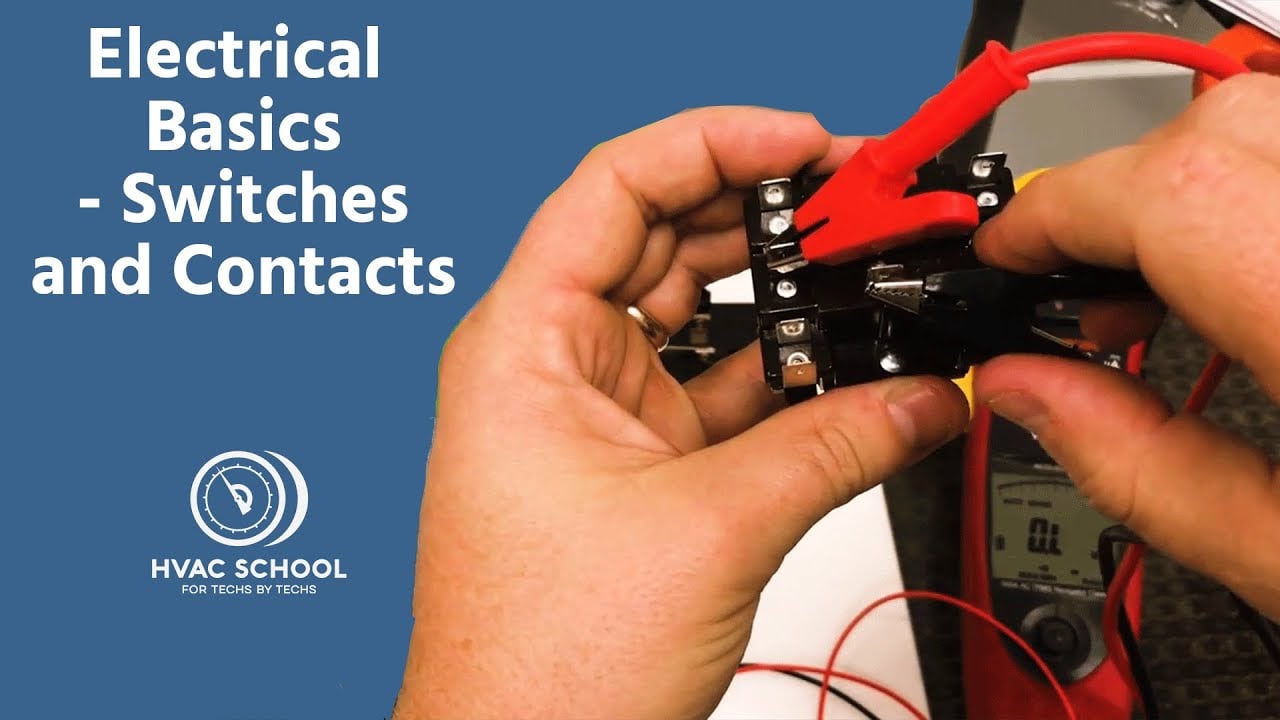
Electrical Basics – Switches and Contacts by HVAC School provides general background. The exact switch and equipment still require their own documentation and validation.
Często zadawane pytania
Czy na podstawie zdjęcia tego przełącznika toggle można określić pozycje zacisków?
Nie. Zdjęcie może pokazywać obudowę i liczbę zacisków, ale nie pozwala na rzetelne ustalenie wewnętrznego układu styków, orientacji widoku, obwodu lampki ani parametrów znamionowych. Należy skorzystać z dokładnego rysunku modelowego i przeprowadzić niezależny test.
Czy wydrukowana wartość amperów dotyczy każdego obciążenia?
Nie. Dopuszczalna wartość zależy od napięcia, prądu przemiennego lub stałego, kategorii obciążenia, prądu włączeniowego, częstotliwości łączeń, temperatury oraz warunków testowych producenta. Należy dokonać wyboru spośród wartości znamionowych podanych dla konkretnego zastosowania.
Czy prónik ciągłości obwodu może być użyty do identyfikacji styków?
Tak, gdy wszystkie źródła są odizolowane, a zgromadzona energia została rozładowana. Przetestuj każdą pozycję, weź pod uwagę, że obwody lamp mogą generować odczyty rezystancji, i porównaj matrycę z dokumentacją producenta.
Czy łącznik powinien bezpośrednio przewodzić prąd silnika lub cewki elektromagnesu?
Tylko wtedy, gdy dokładne obciążenie i cykl pracy mieszczą się w udokumentowanych parametrach znamionowych. W przypadku wyższego prądu rozruchowego, częstej eksploatacji lub maszyn wrażliwych na ryzyko, odpowiednio dobrany przekaźnik lub stycznik jest często lepszym interfejsem.
Jakie informacje powinny znaleźć się w ostatecznej dokumentacji okablowania?
Zarejestruj kod zamówienia, kierunek widoku terminala, matrycę styków, identyfikatory przewodów, urządzenie zabezpieczające, zasilanie, obciążenie, etykiety, wyniki testów, wersje dokumentu i datę zatwierdzenia.
Final verification rule
Approve the installation only when the exact device identity, contact matrix, lamp behavior, mechanical fit, environmental boundary, load rating, protective measures, labels and test results all agree. Resolve every discrepancy before energizing production equipment. Keep the final record with the machine so a later replacement is checked against evidence rather than appearance.



