

An emergency stop button not working can mean several different things: the mushroom will not release, a contact does not change state, the safety controller refuses a reset, or the machine stays stopped after a successful reset. Identify which transition has failed before replacing the button. Mechanical release, safety reset, and machine start are separate events. A released mushroom does not authorize an automatic restart, and a normal controller indicator does not prove the complete safety function. Keep the machine secured under its approved isolation procedure while a qualified person compares the actual device, circuit, and diagnostic information with the machine documentation.
Separate the button problem from the circuit problem
Start with the operator’s description, but turn it into an observable symptom. Ask which station was pressed, whether other stations are latched, whether a guard was opened, what the display reports, and what happened immediately before the fault. Record the order of events. A complaint that the button is “stuck” may actually describe an electrical reset refusal after the button has already released.
A useful diagnostic boundary is the emergency-stop assembly itself. The assembly includes the actuator, mounting parts, contact elements, and their mechanical connection. Beyond that boundary are field wiring, other protective devices, safety inputs, reset logic, output devices, and the machine’s separate run permissions. Do not assume that an alarm containing the words “emergency stop” identifies the faulty component.
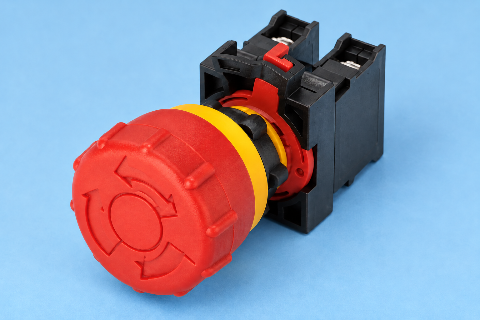
For product identification, compare the installed part with its full order code and the ONPOW emergency-stop product range. A similar red mushroom can have a different release action, contact combination, mounting arrangement, or accessory. Photographs help establish identity; they cannot establish the required safety performance of the complete machine.
When the mushroom does not release
Confirm the release action from the exact product instructions. Twist release, pull release, and key release are different mechanisms. Follow the marked direction and the documented procedure without forcing the actuator. A removable key on one model does not imply that another model releases in the same way.
Inspect only in a condition permitted by the machine’s maintenance procedure. Look for visible impact damage, contamination around the head, an obstructing guard, a loose or displaced mounting assembly, or an accessory pressing against the actuator. Record the condition before cleaning or adjustment. Do not remove a protective cover simply because it makes operation inconvenient; first determine whether it is correctly selected and installed.
If the mechanism feels different from its established normal operation, stop the attempted release and escalate the inspection. Do not lubricate an internal mechanism unless the manufacturer explicitly specifies the method and material. A temporary improvement after forcing or spraying the device does not demonstrate reliable emergency-stop operation.
When the head releases but reset remains unavailable
Read the safety controller’s diagnostic information and the approved circuit diagram together. Determine whether the controller still sees an active demand, mismatched input states, an incomplete reset transition, or an output feedback condition that prevents reset. These states require different investigations.
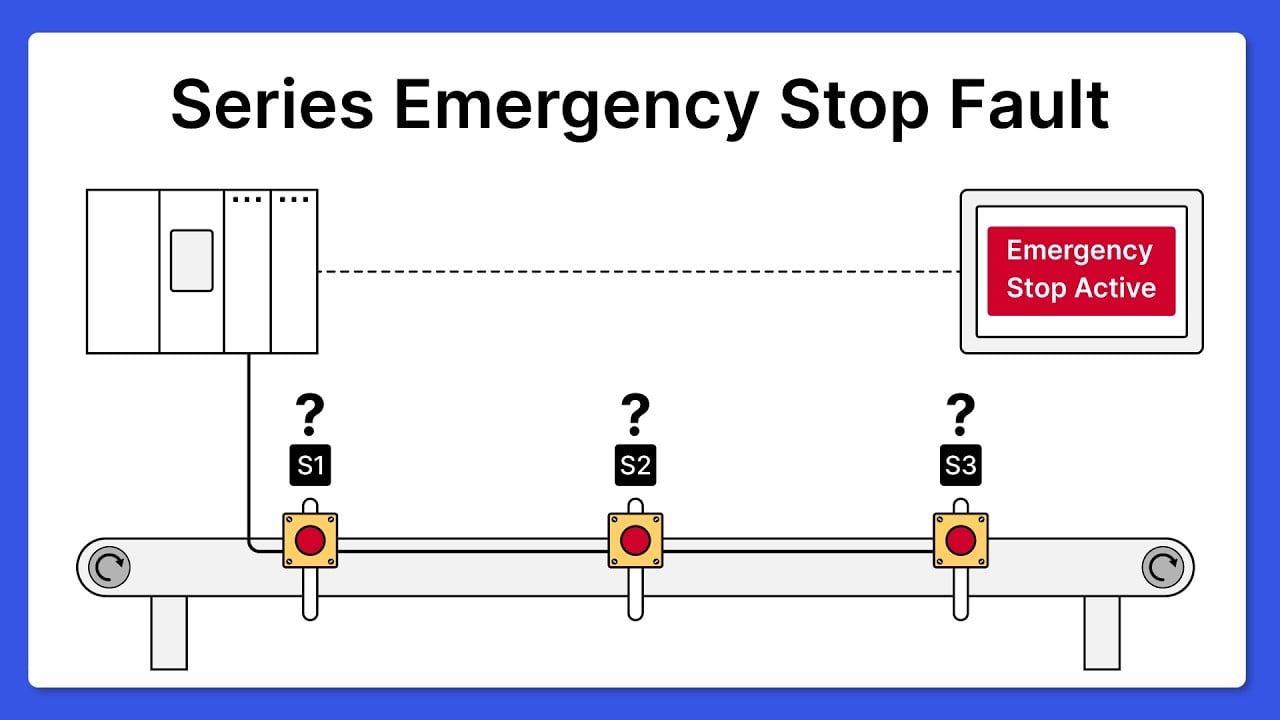
In a machine with several emergency-stop stations, another actuator can remain latched even though the local button has been released. Guard interlocks and other protective functions can also keep the machine stopped. Establish the exact circuit arrangement before attributing the condition to one station. A series arrangement and individually monitored inputs provide different levels of diagnostic detail.
A two-channel circuit can remain inhibited when its channels do not reach the required states within the documented conditions. This observation is a reason to inspect the complete path, rather than a reason to bridge the channels. Channel monitoring, test signals, and reset behavior depend on the actual safety device and configuration. No generic terminal drawing can substitute for the approved diagram.
The reset button may also be involved. A reset input can require a particular press-and-release sequence, supervision, or other conditions. Keep a record of whether the input changes as expected and whether the controller accepts that transition. Repeatedly pressing reset without understanding the refusal hides useful diagnostic information and can create an unsafe expectation of restart.
A decision table for the first investigation
| Observed condition | Evidence to collect | Appropriate investigation boundary |
|---|---|---|
| Mushroom remains mechanically latched | Exact order code, marked release action, obstruction and damage photographs | Actuator, mounting assembly and compatible accessories |
| Mushroom releases but an emergency-stop demand stays active | Station list, input diagnostics and approved circuit revision | Contact elements, field wiring and other stations in the same demand path |
| Input channels disagree | Channel indication, event sequence and wiring identifiers | Each channel and its mechanical/electrical relationship, following controller instructions |
| Inputs appear normal but reset is rejected | Reset input sequence, diagnostic code and controller configuration | Reset conditions and monitored feedback, rather than the mushroom alone |
| Reset succeeds but the machine does not run | Separate run permissions, start command and machine status | Normal control and process permissions after safety reset |
| Fault appears intermittently during vibration or cleaning | Time, operating condition, environmental exposure and inspection record | Mounting, connections, sealing and application compatibility |
This table organizes evidence; it is not a live testing procedure. For U.S. workplaces, 29 CFR 1910.147 addresses hazardous-energy control during servicing, while 29 CFR 1910.333 addresses electrical work practices. Apply the requirements relevant to the actual workplace and task, together with the machine’s approved procedure.
Check contact identity without guessing terminal functions
Use the exact contact diagram and terminal markings. A normally closed safety-path contact and a normally open auxiliary indication contact have different functions. The presence of both on an assembly does not make them interchangeable. See the related explanation of normally open and normally closed emergency-stop contacts for the vocabulary, then verify the actual model.
A disconnected continuity check can support contact identification when performed under an approved procedure, but it does not prove the safety performance of the installed system. Mechanical coupling, direct-opening characteristics where required, controller monitoring, wiring faults, output behavior, and machine stopping response remain separate matters. A meter’s audible indication alone is also an incomplete record; retain the observed values and test conditions when the procedure calls for them.
Check that the correct contact blocks are properly attached to the intended actuator. An apparently compatible block may have a different ordering designation or arrangement. If a block has become detached, do not assume that reattaching it restores an acceptable assembly. Inspect the retention components and follow the manufacturer’s replacement instructions.
Intermittent faults need a condition record
An intermittent reset refusal often becomes difficult to reproduce after the machine has been moved, cleaned, or opened. Record what was happening when the fault appeared: vibration, panel movement, a cleaning cycle, a temperature change, or operation of another protective device. Record the diagnostic message before power cycling when it is safe and permitted to do so.
Compare the installed environment with the exact product’s documented limits and the complete mounting arrangement. A sealing rating for one component does not automatically apply to the panel penetration, accessory, cable entry, or entire enclosure. It also does not establish outdoor suitability, chemical compatibility, or resistance to every cleaning process.
Look for patterns across the maintenance record. Repeated replacement of the same button without investigation can leave the underlying mounting, connection, or environmental problem in place. Conversely, do not conclude that a recurring machine alarm must be a button fault simply because the button is the most visible component.
Replacement information to collect before ordering
Prepare an identification package containing the actuator order code, contact-block order codes, release action, panel mounting details, wiring identifiers, accessory details, and photographs taken before disassembly. Include the machine maker’s replacement specification and any required approval information. Preserve the original wiring record even when terminal labels look obvious.
For ONPOW inquiries, send the application and documentation requirements along with the product identity. Ask for confirmation of the supplied configuration and its documentation rather than requesting “any red emergency button.” A correct component selection still needs integration and validation by the responsible machine designer or qualified team.
The broader emergency-stop selection and assembly guide covers selection context. The comparison of emergency stop and emergency switching off helps prevent replacing one intended function with another. These topics support troubleshooting but do not replace the machine-specific maintenance instructions.
Verify the repaired function before returning the machine
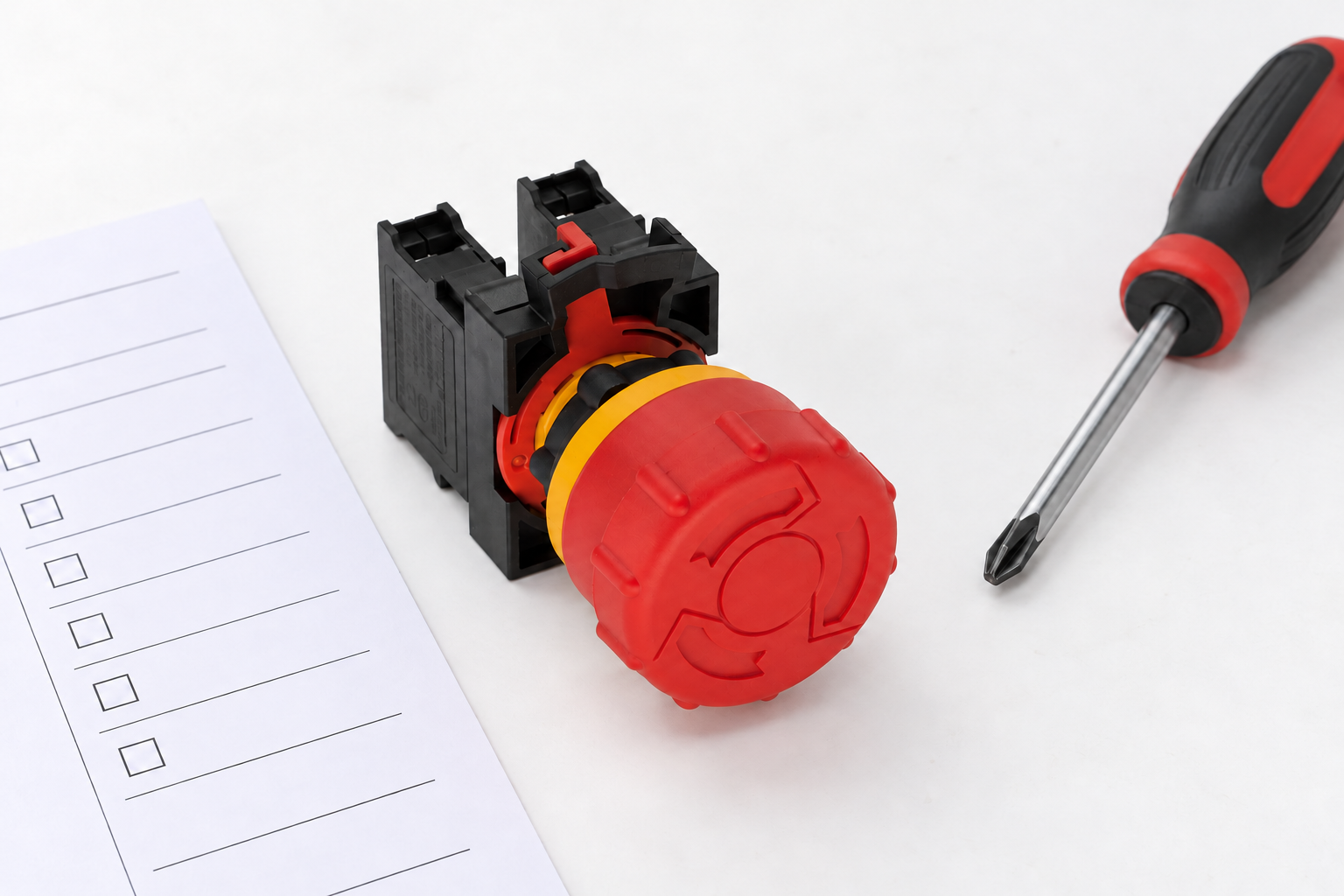
After an authorized repair, compare the completed work with the recorded fault and the approved validation procedure. The checks must cover the relevant actuator operation, input response, reset conditions, output behavior, and stopping function. Confirm the behavior of each affected station rather than checking only the repaired local button.
A successful release should not by itself restart hazardous operation. Separate the release, accepted reset, and subsequent start observations in the maintenance record. Confirm that restoring power or clearing another permission does not produce unexpected behavior under the machine’s specified conditions.
If the original complaint cannot be reproduced or explained, record that limitation. Do not close the repair as a proven component failure merely because a new assembly was fitted. Keep the diagnostic evidence, replaced-part identity, inspection results, and return-to-service authorization together. This gives the next technician a useful baseline if the symptom returns.
For further learning, the following RealPars video discusses diagnosis of a series emergency-stop circuit. It illustrates why the complete demand path matters; its example must not be treated as the wiring specification for another machine.
Watch the RealPars circuit troubleshooting video
Często zadawane pytania
Why will the machine not start after I release the emergency stop?
Releasing the actuator, resetting the safety function, and issuing a machine start command are separate steps. Other safety demands or normal run permissions may still prevent operation. Read the machine’s diagnostic information and approved procedure.
Can I bridge a contact to find the fault?
Do not defeat the emergency-stop path. Use the approved diagnostic procedure, isolation controls, circuit documentation, and controller diagnostics. A bypass can remove protection and does not establish a valid repair.
Does a continuity beep prove that the button is good?
No. It can support a limited contact check under specified conditions. It does not establish the complete assembly’s suitability or validate the installed machine safety function.
Can a waterproof button be used with any cleaning chemical?
No. Check the exact product, seals, accessories, and complete installation for the cleaning conditions. A water-ingress rating alone does not establish chemical compatibility or outdoor suitability.
What should I send when asking for a replacement?
Send the complete actuator and contact-block order codes, release action, panel details, photographs, wiring identifiers, machine specification, and required documentation. Keep the original circuit record so the replacement can be checked against it.



