

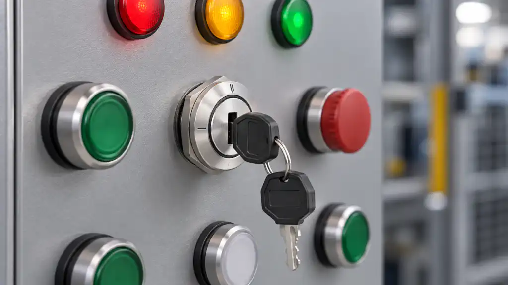
A three-position key switch is not defined by three bezel marks alone. The useful specification is a state table: what each contact does in the left, center, and right positions; whether each position is maintained or spring-return; and where the key can be removed. For industrial panels, this is often used to authorize modes such as setup–off–run or local–off–remote. It should not be confused with a vehicle ignition switch, even though many current search results use similar wording. This guide shows how to document and verify industrial contact logic without guessing from the front appearance.
What “three-position” actually tells you
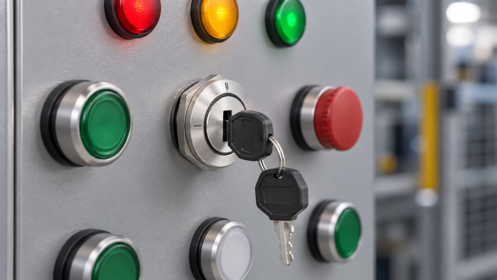
Three-position describes the operator’s mechanical travel. It does not, by itself, identify the circuit, the number of poles, the contact sequence, the spring-return direction, or the key-removal rule. Two products can both have left–center–right movement and still behave differently electrically.
The official ONPOW LAS0-K30 catalog lists three-position maintained, half-return, and return action patterns for key-switch variants. It also lists several contact structures for the family, including combinations of normally open and normally closed contacts. Those family options are useful evidence that the operating action and contact pack must be ordered separately and verified together. They are not permission to infer the terminals on an unidentified sample.
The front legend should describe the machine function, while the rear diagram describes the contact function. Procurement needs both. If either is missing, keep the item open rather than translating a visual impression into a wiring instruction.
Start with a position-by-position truth table
Write the required behavior before choosing a part. The table below is an illustrative requirement, not the terminal diagram for a specific ONPOW order code. A designer could use it for a controller that expects separate Local and Remote requests with the center position as Off.
| Key position | LOCAL input | REMOTE input | Intended command | What must be verified |
|---|---|---|---|---|
| Left | Zamknięte | Otwórz | Local control enabled | Exact contact and terminal pair close only in this position |
| Center | Otwórz | Otwórz | Both mode requests removed | Center is a stable position and neither request remains active |
| Right | Otwórz | Zamknięte | Remote control enabled | Exact contact and terminal pair close only in this position |
Another machine may require a common contact to transfer between two outputs, or may monitor an additional status contact. That is a different truth table. “ON–OFF–ON” is helpful shorthand, but it is not enough for design approval because it does not identify poles, commons, transition timing, or normal reference state.
For every signal, record the input name, source voltage, terminal pair, expected state in all three positions, and response when the operator releases the key. If a PLC reads the switch, also define how the program responds to an impossible combination such as Local and Remote active at the same time.
Maintained, half-return, and full-return actions
A maintained operator stays in the selected position after the hand releases it. This is suitable when the physical selector should continue showing the chosen mode. A spring-return position moves back when released. It is suitable for a temporary command such as reset, jog, or request-to-start, provided the complete control logic is designed for that function.
On a three-position device, return behavior may be symmetrical or asymmetrical. One outer position can be momentary while the center and other outer position are maintained. The ONPOW catalog calls out maintained, half-return, and return patterns, but the small action diagram and exact order code remain the authority. Write the required movement in words—for example, “right returns to center; left and center maintained”—instead of relying only on a generic label.
Spring return changes the command duration; it does not turn an ordinary control circuit into a safety function. A returned key also does not prove that downstream equipment has stopped or hazardous energy has been isolated.
Contact blocks, poles, and normal state
The key rotates a mechanism that actuates the rear contact system. A normally open contact is open in its defined normal state, while a normally closed contact is closed in that state. On selector devices, the manufacturer’s reference position and contact chart are essential because “normal” should not be improvised from whichever position the installer happens to see.
One pole switches one independent circuit. More poles allow independent signals to be controlled by the same operator. Yet pole count still does not define which positions operate each pole. A contact table or cam diagram is required.
When comparing an assembled sample with documentation:
- match the full order code, not just the metal head;
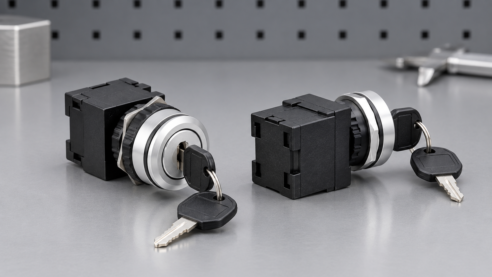
- identify each removable or integral contact block;
- locate the manufacturer’s common, NO, and NC markings;
- trace the position chart for every pole;
- confirm whether contacts change before, at, or after the mechanical detent;
- verify continuity with power removed before field wiring.
How to verify the contact logic safely
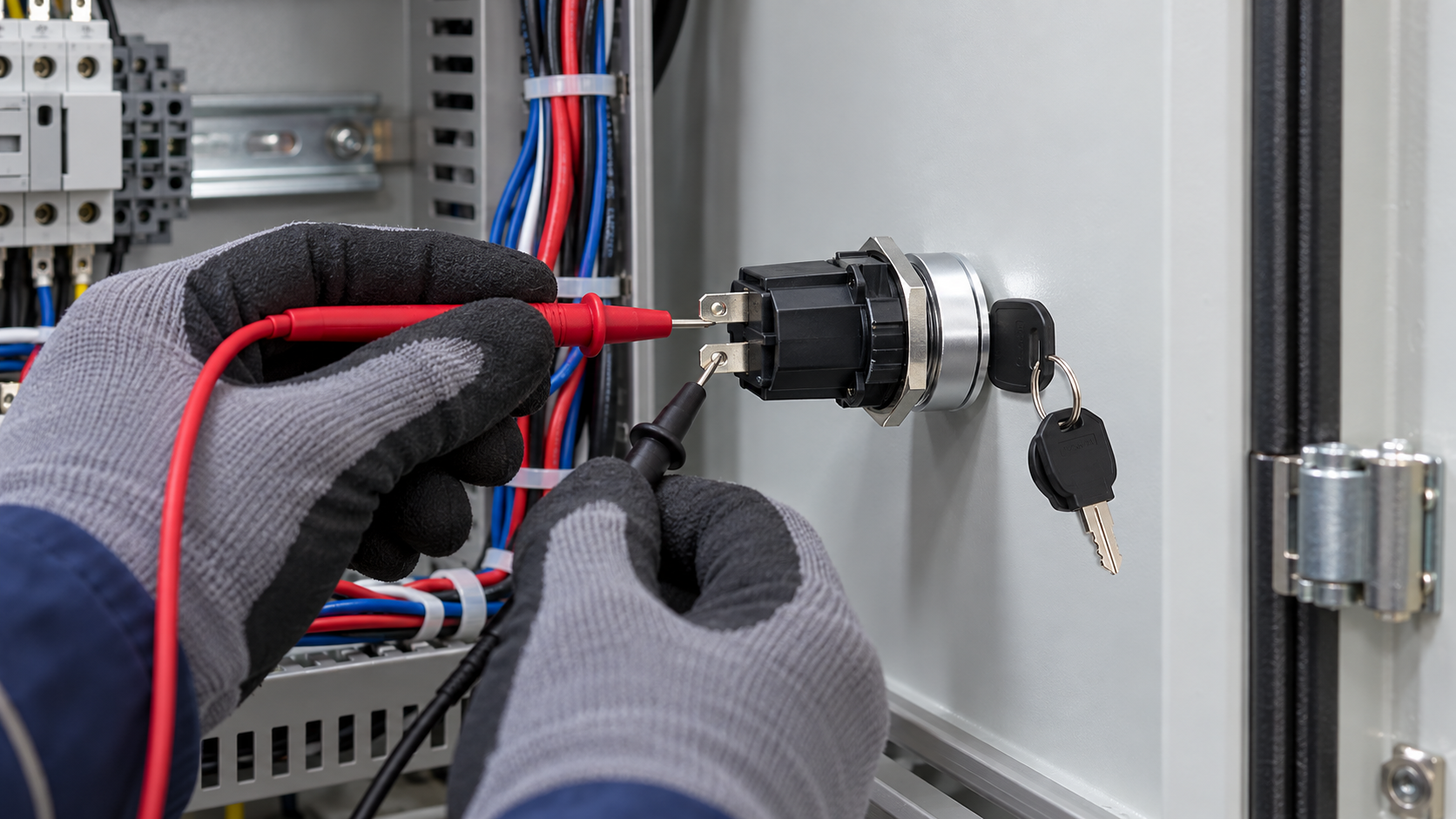
First isolate the control circuit according to the machine’s approved procedure and verify absence of voltage with suitable equipment. OSHA explains that control-circuit devices, including selector switches, are not energy-isolating devices. The key switch therefore must not be treated as the disconnect used to make testing safe.
Next, compare the received part with the approved drawing and order code. Photograph or record the rear markings, but do not publish or depend on a photograph when the manufacturer drawing is available. Connect a continuity tester only to the terminal pair being checked. Turn the key through left, center, and right, then repeat the sequence while allowing every return position to release naturally.
Record closed and open states in a test sheet. Repeat for every pole. Test slowly enough to observe transition behavior, but do not assume a handheld meter can characterize contact timing precisely. If break-before-make or make-before-break behavior matters, obtain explicit manufacturer data and use an appropriate test method.
Finally, test the switch as part of the complete control system. Confirm that legends match actual machine responses, loss and restoration of power do not cause an unintended restart, and conflicting inputs are handled as designed. Keep the measurement record with the machine documentation.
Key removal is a separate decision
Some keyed selectors allow key removal in one position; others allow removal in several. That option affects access management and operating discipline, but it does not create a lockout device or a validated safety function.
Define who holds the key, when it can be removed, whether multiple identical keys exist, and what happens after a power interruption. If the key can be removed in a run mode, the machine may remain selected after the authorized person leaves. If it can only be removed in center, the operator may have to cancel the mode before leaving—but the actual circuit still needs verification.
Do not assume removal positions from the catalog photograph. Ask for the exact key-removal chart tied to the proposed order code and confirm it on the received sample.
Common specification errors
Treating three front positions as three terminals
Position count and terminal count are unrelated. The contact arrangement can require more terminals, and multiple poles add independent circuits. Use the contact diagram.
Copying an automotive ignition diagram
Current Google results for three-position key switches contain many ignition products. Their OFF–RUN–START intent, current demands, and terminal conventions do not automatically apply to an industrial panel selector. Select the industrial control device and its documented contact blocks for the actual circuit.
Assuming center is always OFF
Center may be a valid maintained command or part of a spring-return pattern. “Center off” must appear in the functional requirement and be confirmed by the exact chart.
Using the key as an isolator
A selector command can tell a control system to stop; it does not necessarily disconnect hazardous energy. Follow the machine’s energy-control and electrical isolation design.
Checking only one pole
Every pole and every position needs a recorded result. A correct first contact does not prove the rest of the contact pack or wiring.
Selection and RFQ checklist
Send the supplier a complete requirement rather than “three-position key switch” alone:
- The left, center, and right legends and the machine function behind each.
- Maintained or spring-return behavior for every position.
- Required key-removal position or positions.
- A contact truth table for each pole.
- Control voltage, load type, and interface device.
- Panel cutout, thickness, rear clearance, anti-rotation requirement, and enclosure conditions.
- Required documentation, markings, certificates, quantity, and sample-validation plan.
- The exact manufacturer drawing and order code to be approved.
Ten ONPOW key/selector switch range i ONPOW key-switch product page provide the relevant product-family starting point. For the simpler two-state decision, see two-position key switches: maintained and spring return. The broader selector-switch types guide explains operator categories, and the key-operated selector contact-layout guide adds panel-design context.
Film edukacyjny
The following neutral animation explains generic selector-switch operation. It is useful background, but it does not replace the three-position contact chart for the ordered part.
Często zadawane pytania
Is a three-position key switch always ON–OFF–ON?
No. Three positions describe mechanical travel. The electrical states and spring-return behavior depend on the exact operator and contact configuration.
Can the center position be momentary?
It can only be treated that way when the manufacturer’s action chart for the exact order code says so. Many designs instead use a stable center with one or both outer positions returning to center.
How do I identify the common terminal?
Use the terminal marking and manufacturer diagram, then verify the exact assembly with power removed. Do not identify a common by terminal location or a generic internet diagram.
Does key control make the selector a safety switch?
No. A key can restrict casual operation, but the safety function and hazardous-energy isolation must be designed and validated separately.
Ostateczna decyzja
Approve a three-position key switch only after the mechanical action, key-removal rule, and contact truth table all match the machine requirement. Verify the exact order code and sample through all three positions before energizing the panel. To request a matched ONPOW configuration, send the state table, panel drawing, load information, and return-action requirement through the contact page.
Sources for verification: ONPOW LAS0-K30 catalog; IEC 60947-5-1:2024 scope for control-circuit devices and switching elements; OSHA energy-control circuitry prohibition; Rockwell Automation selector-operator catalog.
Customization
ONPOW undertakes a variety of custom needs for push-button development. Confirm whether packaging, marking or documentation OEM/ODM applies to Three-Position Key Switch Contact Logic Explained in the quotation.
Minimum order quantity, lead time and trade terms are not published here; confirm them with sales at sales@onpow.com.



