

A dual push button switch puts two command actions into one panel location; for a typical start/stop station, the contact functions, control circuit, and front-panel IP requirement must be specified before selecting the operator. A green/red layout is useful only when its individual contacts and the controlled equipment match the circuit design. For a 22mm panel, confirm the actual mounting dimensions and the exact model data rather than relying on colour or a generic size label.
Part 1. What does a dual push button switch do on a 22mm panel?
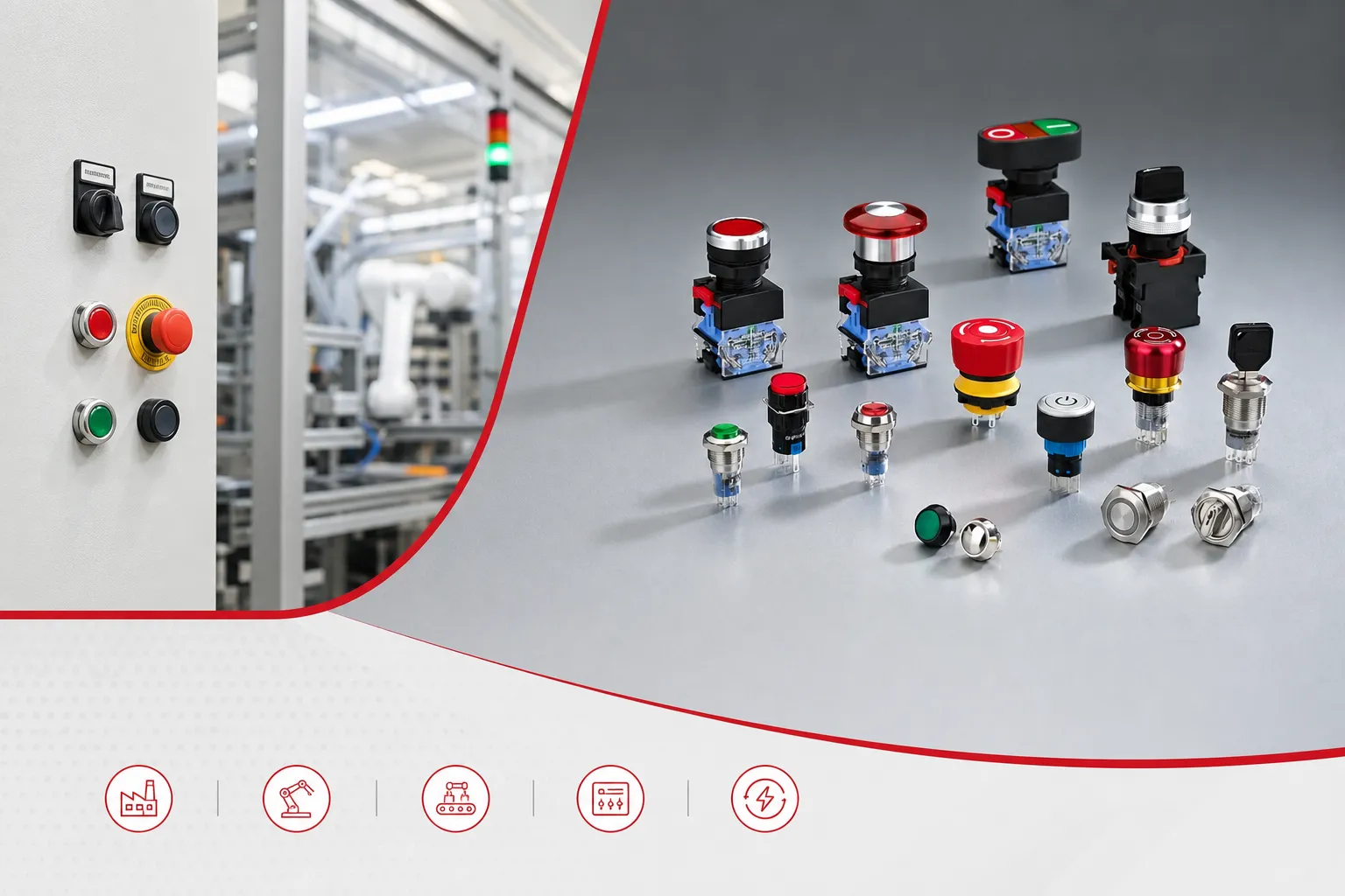
A dual operator groups two separate manual actions in a compact station. In machine-control language, the actions are often labelled Start and Stop or use green and red caps. The operator does not, by itself, define what happens after either button is released: that depends on the contact blocks and the circuit behind them.
For a conventional manual motor-control circuit, a momentary start contact energizes a coil and an auxiliary contact maintains the coil after the operator is released. A stop contact opens the coil path and drops the contactor. Control.com’s motor-starter explanation illustrates that control-circuit principle; it is not a wiring diagram for every machine.
The real question is therefore not “is it a green/red button?” but “which contacts are fitted, what do they operate, and what should occur after loss of control power?” The user question, “does it close the contacts when green is pushed and keeps it closed until red is pushed?”, is a useful reminder that the operator action and the electrical latch are separate design decisions.
| Panel requirement | Verify before selection | Почему это важно |
|---|---|---|
| Command function | Start, Stop, reset, or another action | Labels alone do not define circuit logic |
| Функция связи | NO, NC, or a documented combination | The circuit needs the intended state at rest |
| Control supply | Coil/control voltage and circuit type | The operator must suit the actual command circuit |
| Panel interface | Hole, thickness, clearance, and rear depth | A nominal 22mm description is not a full mechanical drawing |
For wider context on the common panel size, see the 22mm push button switch guide.
Part 2. Which start and stop contacts should the circuit use?
In a common three-wire control arrangement, Start is a normally open (NO) contact. Pressing it completes the control path long enough to energize the contactor coil.
Stop is normally closed (NC), so opening it removes coil power. A normally open auxiliary contact on the contactor is then placed in parallel with Start to create the seal-in path.
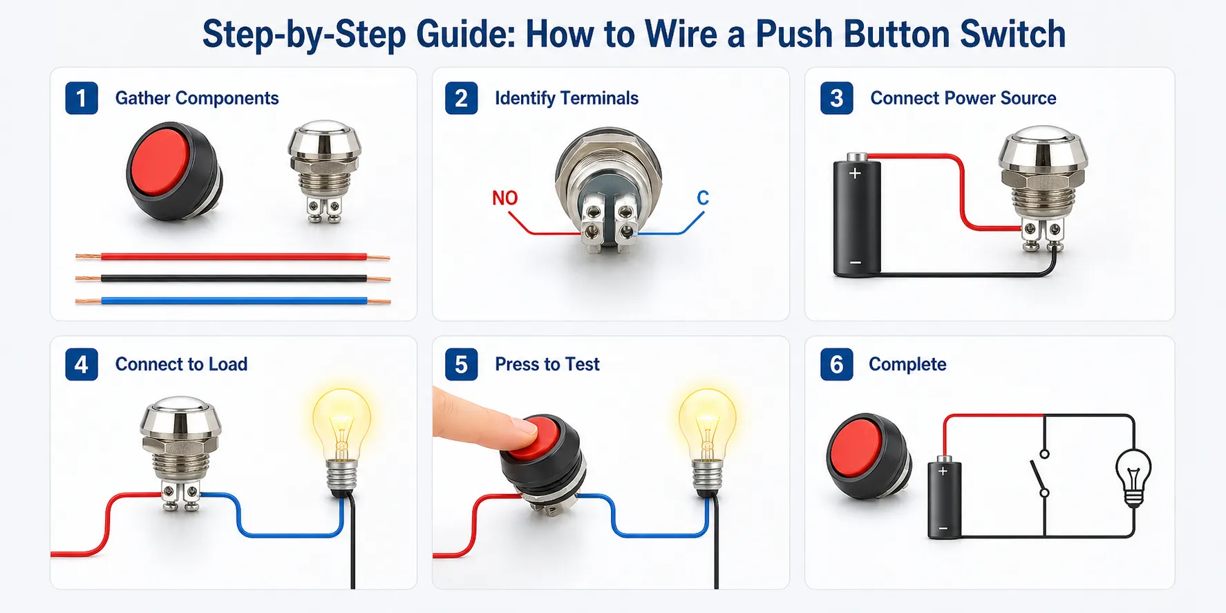
That arrangement answers a frequent need, but it is not permission to assume that every dual push button contains one NO and one NC contact. A product order should state the required contact arrangement, number of circuits, and whether the operator must be momentary or maintained. The push button switch wiring and installation guide is a useful related reading link when the panel designer is documenting connections.
| Desired behaviour | Typical circuit element | What to confirm |
|---|---|---|
| Initiate a control command | NO start contact | Coil voltage and auxiliary seal-in method |
| Interrupt a held coil | NC stop contact | Contact state at rest and the required stop behaviour |
| Show a machine condition | Separate lamp/indicator circuit | Lamp voltage, colour, and logic source |
| Add safety functions | Purpose-designed safety architecture | Required risk assessment and applicable standards |
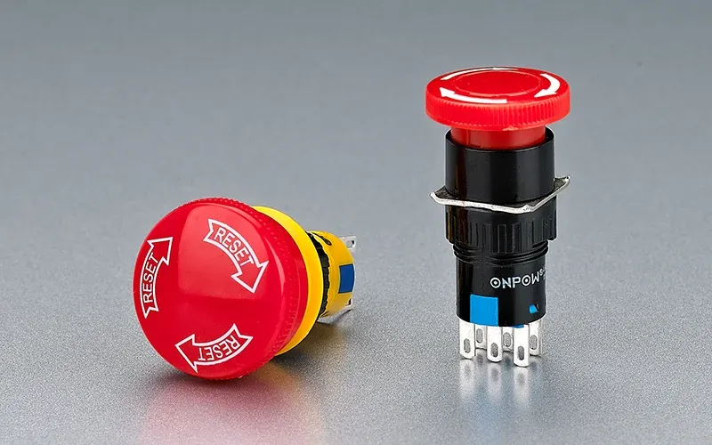
Важно: A regular stop command is not automatically an emergency-stop function. Do not apply an E-stop label or safety claim to a dual button unless the complete safety function, device, and machine design have been evaluated for that purpose. (IEC 60947-5-1)
Part 3. How should a 22mm start/stop layout fit the panel?
Panel space is the first mechanical filter. The front face must be readable and reachable, while the rear has to accommodate contact blocks, wiring bends, and any terminals. Measure the drawing and the panel material rather than treating every 22mm product as mechanically interchangeable.
Group the two actions where the operator can distinguish them without searching the panel. This is especially useful on compact control boxes, but spacing, legends, and accidental-operation risk remain system-level decisions. When illumination is part of the requirement, specify the lamp circuit separately; 12V vs 24V illuminated push buttons explains why the LED supply is not interchangeable by appearance.
The 22mm hole is an interface, not a performance statement. It does not establish the contact duty, the panel-seal rating, the assembly torque, or the accessory compatibility. Keep the product drawing, panel drawing, and wiring schedule together during review.
Part 4. What does the IP option actually protect?
An IP marking describes ingress protection for a defined product configuration; it is not a generic attribute of all 22mm devices. Schneider Electric’s 22mm push-button FAQ demonstrates the point by reporting IP values for named series, while its conformity FAQ separates operator protection from terminal protection.
Start with the front exposure: dry indoor dust, splash, washdown, or another documented environment. Then check the stated protection boundary—front operator, full assembly, or terminal region—and whether a gasket, boot, enclosure, or installation condition is part of the rating.
| Вопрос | Good RFQ wording | Avoid |
|---|---|---|
| Front exposure | “Specify required front-panel ingress level for installed operator.” | “Need waterproof.” |
| Panel interface | “Provide panel material, thickness, and cutout drawing.” | “22mm fits.” |
| Terminal area | “Confirm rear/terminal protection required inside enclosure.” | “IP on the button covers the whole cabinet.” |
| Очистка экспозиции | “Describe liquid, pressure, frequency, and direction of exposure.” | “High IP is always enough.” |
This separates the operator’s stated protection from the enclosure design. It also prevents a purchaser from substituting an unrelated product simply because it has a more impressive IP number.
Part 5. When should a dual push button control a contactor instead of a load?
Where a machine load needs a purpose-selected power-switching device, use the dual button as a control input to the contactor coil rather than declaring the button a direct-load switch. The contactor and overload arrangement must be selected for the actual load, supply, duty category, protection scheme, and machine design.
This boundary matters because a button’s thermal or insulation value is not a complete switched-load specification. Arc interruption, inductive load duty, operation frequency, inrush, wiring, short-circuit protection, and enclosure temperature can all change the suitable device choice. The control button remains valuable: it provides the local command; the contactor supplies the power switching in a properly engineered circuit.
Из поля: A user asked whether the green button “keeps it closed until red is pushed.” That concern is best answered by documenting the auxiliary seal-in circuit, not by assuming a latching dual operator. — Electronics Stack Exchange discussion
Part 6. When does the HBY5J-10 fit the documented requirement?
Земля ONPOW HBY5J-10 dual push button is a candidate when the buyer needs its documented interface and confirms every required function. Its page lists Ui 660V and Ith 10A, with front protection IP40 and IP65 made to order. It also lists ABS for the button, a Zn-Al alloy body, a PBT base, and silver-alloy contacts.
Those are model-page fields, not a blanket approval for direct switching or a substitute for a stated operational switching category. The installation must still be matched to the exact contact arrangement, circuit, and environment.
The page also lists mechanical and electrical life figures and test values. Compare its published details with the metal vs plastic push buttons discussion only as a selection aid; material is not a shortcut for duty or ingress.
Fit Boundary: HBY5J-10 is appropriate for a buyer who has verified the panel interface, required control function, protection option, and model-specific data. It is not appropriate when a project requires an unverified direct-load rating, a known safety function, or a different contact/IP configuration.
Part 7. What should the RFQ include?
A quote request becomes actionable when it describes the control function instead of just asking for a “dual switch.” Include the fields below so the supplier can map the request to a documented configuration.
| Buyer should provide | Почему это важно | Common mistake |
|---|---|---|
| Panel drawing, hole, thickness, and rear clearance | Confirms mechanical fit | Sending only “22mm” |
| Start/stop action and required NO/NC contacts | Defines circuit behaviour | Assuming colours define contacts |
| Control voltage and device being controlled | Separates command circuit from load | Calling Ith the load rating |
| Front exposure and required IP option | Selects stated protection boundary | Requesting “waterproof” without conditions |
| Illumination and legend requirement | Identifies lamp and marking details | Omitting lamp supply |
| Quantity and documentation needs | Supports sourcing review | Treating all regional requirements as automatic |
For a documented configuration discussion, contact ONPOW with control-panel requirements. Include the circuit purpose and environmental requirement in the first message so the enquiry can be checked against the exact model.
Часто задаваемые вопросы
What is a dual push button switch?
A dual push button switch combines two separate manual actions in one panel operator. The actual contact functions, action type, and circuit result must be confirmed from the specific configuration.
Do start and stop buttons normally use NO and NC contacts?
A common contactor control circuit uses NO for Start and NC for Stop, but a purchase order must specify the actual contact arrangement required.
Does a 22mm operator fit every 22mm panel?
No. Confirm the product drawing, permitted panel thickness, rear clearance, locating features, and installation hardware.
Is a red/green dual button automatically latching?
No. The buttons may be momentary; a contactor auxiliary contact or other circuit logic can provide the held state.
Does IP65 mean the whole control box is IP65?
No. Check the stated boundary. An operator’s front-panel rating does not automatically rate the enclosure, cable entries, or terminals.
Can this dual button switch a motor directly?
Do not decide that from colours, size, Ui, or Ith. Use a documented operational switching category and complete circuit design; use a contactor control circuit where the load requires it.
What should I send for an HBY5J-10 quotation?
Send the desired contact function, panel details, control voltage, exposure/IP requirement, illumination need, quantity, and any required documentation.



