

A three-position toggle switch must be specified by its contact sequence, not only by the number of lever positions. ON-OFF-ON disconnects the common in the center. ON-ON-ON uses a special progressive or crossover contact pattern. ON-ON is normally a two-position description, so confirm the manufacturer contact table before assigning functions. This guide explains a safe identification and verification process for engineers, panel builders, maintenance teams and buyers. It does not replace the current datasheet, machine risk assessment or locally applicable electrical requirements. The method keeps each decision traceable during purchasing, assembly, commissioning and later service.
Quick decision
Start with function, not pin count. Write the required stable and momentary states, identify every contact and lamp circuit, then match the documented rating to the actual load. Keep power isolated during identification. After installation, test both the electrical state and the machine response. If the application controls hazardous motion, use the required safety architecture rather than treating a general-purpose switch as a complete safety function.
Selection and wiring criteria
| Decision | Nelerin doğrulanması gerekiyor | Mühendislik gerekçesi |
|---|---|---|
| Position count | Confirm three mechanically distinct detents | Three positions do not reveal the electrical state. |
| Center function | State OFF, connected or transitional behavior | The center position often determines safe mode selection. |
| Contact sequence | Obtain the connection matrix for each pole | ON-ON-ON patterns vary and cannot be inferred from six terminals. |
| Maintained or momentary | Record which positions latch and which spring back | Parentheses in catalog notation often indicate momentary action. |
| Break-before-make | Confirm transfer timing if sources or modes must not overlap | Temporary overlap or interruption can affect the controlled system. |
| Labeling | Use functional legends rather than unexplained ON words | Operators need to know the machine command, not internal contact jargon. |
| Interlocking | Implement required logic outside the operator when needed | A selector alone may not prevent incompatible outputs. |
| Commissioning | Test all transitions, including rapid movement through center | The controller response must remain predictable between detents. |
This table is intentionally qualitative. Numerical ratings, torque, conductor size, insulation distance, endurance and environmental limits must come from the approved documents for the exact device and from the complete equipment design. Similar-looking switches can use different internal connections.
Understand the contact logic before wiring
Pole describes how many independent common contact paths operate together. Throw describes how many fixed contacts each common can select. These terms do not state the number of lever positions, whether a position is maintained or momentary, whether contacts overlap during transfer, or how an indicator lamp is connected. Those details require a position-by-position contact table.
Draw a matrix with terminals across the top and actuator positions down the side. Mark only connections supported by the current drawing or by isolated measurements. Include a clear viewing direction such as “rear terminal view with actuator up.” This simple record prevents mirrored diagrams, rotated components and harness cavity numbers from being confused during assembly or later service.
Position count
Neyin doğrulanacağı: Confirm three mechanically distinct detents. Three positions do not reveal the electrical state. The engineering record should name the exact order code, drawing revision, supply, load and operating state used for the decision. Check the component in its installed orientation because panel thickness, wire routing, adjacent hardware and actuator access can change the result.
How to verify it: Compare the current manufacturer contact diagram with an isolated continuity test. Record the measured state before operation, in every maintained position and after release from every momentary position. If documentation and measurement disagree, stop and resolve the mismatch before applying power. Never infer a terminal function from pin location, metal color or a diagram for a similar-looking switch.
Center function
Neyin doğrulanacağı: State OFF, connected or transitional behavior. The center position often determines safe mode selection. The engineering record should name the exact order code, drawing revision, supply, load and operating state used for the decision. Check the component in its installed orientation because panel thickness, wire routing, adjacent hardware and actuator access can change the result.
How to verify it: Compare the current manufacturer contact diagram with an isolated continuity test. Record the measured state before operation, in every maintained position and after release from every momentary position. If documentation and measurement disagree, stop and resolve the mismatch before applying power. Never infer a terminal function from pin location, metal color or a diagram for a similar-looking switch.
Contact sequence
Neyin doğrulanacağı: Obtain the connection matrix for each pole. ON-ON-ON patterns vary and cannot be inferred from six terminals. The engineering record should name the exact order code, drawing revision, supply, load and operating state used for the decision. Check the component in its installed orientation because panel thickness, wire routing, adjacent hardware and actuator access can change the result.
How to verify it: Compare the current manufacturer contact diagram with an isolated continuity test. Record the measured state before operation, in every maintained position and after release from every momentary position. If documentation and measurement disagree, stop and resolve the mismatch before applying power. Never infer a terminal function from pin location, metal color or a diagram for a similar-looking switch.
Maintained or momentary
Neyin doğrulanacağı: Record which positions latch and which spring back. Parentheses in catalog notation often indicate momentary action. The engineering record should name the exact order code, drawing revision, supply, load and operating state used for the decision. Check the component in its installed orientation because panel thickness, wire routing, adjacent hardware and actuator access can change the result.
How to verify it: Compare the current manufacturer contact diagram with an isolated continuity test. Record the measured state before operation, in every maintained position and after release from every momentary position. If documentation and measurement disagree, stop and resolve the mismatch before applying power. Never infer a terminal function from pin location, metal color or a diagram for a similar-looking switch.
Break-before-make
Neyin doğrulanacağı: Confirm transfer timing if sources or modes must not overlap. Temporary overlap or interruption can affect the controlled system. The engineering record should name the exact order code, drawing revision, supply, load and operating state used for the decision. Check the component in its installed orientation because panel thickness, wire routing, adjacent hardware and actuator access can change the result.
How to verify it: Compare the current manufacturer contact diagram with an isolated continuity test. Record the measured state before operation, in every maintained position and after release from every momentary position. If documentation and measurement disagree, stop and resolve the mismatch before applying power. Never infer a terminal function from pin location, metal color or a diagram for a similar-looking switch.
Labeling
Neyin doğrulanacağı: Use functional legends rather than unexplained ON words. Operators need to know the machine command, not internal contact jargon. The engineering record should name the exact order code, drawing revision, supply, load and operating state used for the decision. Check the component in its installed orientation because panel thickness, wire routing, adjacent hardware and actuator access can change the result.
How to verify it: Compare the current manufacturer contact diagram with an isolated continuity test. Record the measured state before operation, in every maintained position and after release from every momentary position. If documentation and measurement disagree, stop and resolve the mismatch before applying power. Never infer a terminal function from pin location, metal color or a diagram for a similar-looking switch.
Interlocking
Neyin doğrulanacağı: Implement required logic outside the operator when needed. A selector alone may not prevent incompatible outputs. The engineering record should name the exact order code, drawing revision, supply, load and operating state used for the decision. Check the component in its installed orientation because panel thickness, wire routing, adjacent hardware and actuator access can change the result.
How to verify it: Compare the current manufacturer contact diagram with an isolated continuity test. Record the measured state before operation, in every maintained position and after release from every momentary position. If documentation and measurement disagree, stop and resolve the mismatch before applying power. Never infer a terminal function from pin location, metal color or a diagram for a similar-looking switch.
Commissioning
Neyin doğrulanacağı: Test all transitions, including rapid movement through center. The controller response must remain predictable between detents. The engineering record should name the exact order code, drawing revision, supply, load and operating state used for the decision. Check the component in its installed orientation because panel thickness, wire routing, adjacent hardware and actuator access can change the result.
How to verify it: Compare the current manufacturer contact diagram with an isolated continuity test. Record the measured state before operation, in every maintained position and after release from every momentary position. If documentation and measurement disagree, stop and resolve the mismatch before applying power. Never infer a terminal function from pin location, metal color or a diagram for a similar-looking switch.
Safe identification and commissioning sequence
- Define the function. State what each actuator position should command, what happens on release and what the normal state must be after loss of power.
- Confirm identity. Photograph the marking and record the complete order code. Retrieve the matching current drawing rather than a family brochure.
- Isolate energy. Follow the site procedure for disconnecting and controlling hazardous energy. Prove the circuit is de-energized with appropriate equipment before touching conductors.
- Separate the component. Disconnect enough conductors to prevent parallel circuit paths from corrupting continuity measurements. Label every removed conductor.
- Map contacts. Test all terminal pairs in all positions. Repeat the sequence to detect intermittent behavior and note any spring-return action.
- Identify lamps separately. Use the published lamp diagram and voltage. Do not apply an unknown test voltage to an LED or electronic module.
- Review the load. Check normal current, inrush, AC or DC, inductive energy, switching frequency, protection and the consequence of a contact failing open or closed.
- Install mechanically. Confirm cutout, panel thickness, anti-rotation, fasteners, sealing, rear clearance, conductor support and accessible labels.
- Perform an unpowered check. Verify point-to-point wiring and insulation before energizing. Make sure unused terminals cannot contact adjacent conductive parts.
- Commission under control. Energize according to the equipment procedure, test each command and indication, then test loss and restoration of power and the credible faults identified by the risk assessment.
Load and protection boundaries
Contact ratings are conditional. A resistive laboratory load does not represent every motor, solenoid, lamp, heater, electronic power supply or capacitive input. DC interruption can sustain an arc differently from AC. Inductive loads release stored energy when opened, and cold lamps or capacitors may draw high inrush. Obtain the load data and apply only a rating that explicitly covers the intended conditions.
The switch is also not the branch-circuit protective device. Conductor size, fuse or breaker selection, short-circuit capability, grounding, insulation and enclosure protection belong to the wider equipment design. Where the operator should carry only a low-energy command, use a properly selected relay, contactor or controller input and verify the interface. Suppression components must suit the supply, load and failure behavior.
Common mistakes
- Position count: Three positions do not reveal the electrical state. Prevent this by completing the related verification step—confirm three mechanically distinct detents—and retaining the evidence with the machine documentation.
- Center function: The center position often determines safe mode selection. Prevent this by completing the related verification step—state off, connected or transitional behavior—and retaining the evidence with the machine documentation.
- Contact sequence: ON-ON-ON patterns vary and cannot be inferred from six terminals. Prevent this by completing the related verification step—obtain the connection matrix for each pole—and retaining the evidence with the machine documentation.
- Maintained or momentary: Parentheses in catalog notation often indicate momentary action. Prevent this by completing the related verification step—record which positions latch and which spring back—and retaining the evidence with the machine documentation.
- Break-before-make: Temporary overlap or interruption can affect the controlled system. Prevent this by completing the related verification step—confirm transfer timing if sources or modes must not overlap—and retaining the evidence with the machine documentation.
- Labeling: Operators need to know the machine command, not internal contact jargon. Prevent this by completing the related verification step—use functional legends rather than unexplained on words—and retaining the evidence with the machine documentation.
What to include in an RFQ
Provide the contact form, actuator positions, maintained or momentary action, center state, lamp function and voltage, supply, load category, normal and inrush current, switching frequency, panel cutout, panel thickness, rear-space limit, terminal preference, environment, ingress requirement, temperature range, vibration, required documentation, quantity and target market. Ask the supplier to return the exact contact table and dimensional drawing for the proposed order code.
Use the ONPOW industrial control product range to identify candidate families. Final selection must be based on the exact model documentation and validation in the completed assembly. For an unusual harness or control sequence, provide a terminal-view sketch and ask the supplier to mark any assumptions before samples are ordered.
Related ONPOW guides
- Toggle switch position basics
- Toggle switch and push button comparison
- Normally open and normally closed contacts
Authoritative references
- IEC 60947-5-1 control-circuit devices
- IEC 60204-1 electrical equipment of machines
- OSHA electrical safety requirements
Educational video
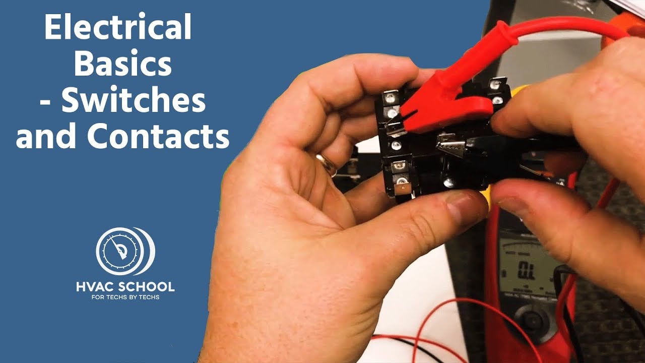
Electrical Basics – Switches and Contacts by HVAC School provides general background. The exact switch and equipment still require their own documentation and validation.
Frequently asked questions
Bu basmalı düğmenin fotoğrafından terminal konumları belirlenebilir mi?
Hayır. Bir fotoğraf paketi ve terminal sayısını gösterebilir, ancak iç kontak düzenini, görüş yönünü, lamba devresini veya değeri güvenilir bir şekilde ortaya koyamaz. Tam model çizimini ve izole bir test kullanın.
Basılan amper değeri her yük için geçerli mi?
Hayır. İzin verilen değer; gerilime, AC veya DC olmasına, yük kategorisine, kalkış akımına, anahtarlama frekansına, sıcaklığa ve üretici test koşullarına bağlıdır. Gerçek uygulama için belirtilen nominal değerlerden birini seçin.
Bir süreklilik test cihazı kontakları tanımlamak için kullanılabilir mi?
Evet, tüm kaynaklar izole edildiğinde ve depolanan enerji deşarj edildiğinde. Her pozisyonu test edin, lamba devrelerinin direnç okumaları üretebileceğini kabul edin ve matrisi üretici belgeleriyle karşılaştırın.
Anahtar, doğrudan bir motor veya selenoid akımını taşımalı mı?
Yalnızca tam yük ve çalışma döngüsü belgelenen nominal değerler dahilinde olduğunda. Daha yüksek kalkış akımı, sık çalışma veya risk duyarlı makineler için, uygun şekilde seçilmiş bir röle veya kontaktör genellikle daha iyi bir arayüzdür.
Nihai kablolama kaydında hangi bilgiler yer almalıdır?
Sipariş kodunu, terminal görünüm yönünü, kontak matrisini, iletken tanımlayıcılarını, koruma cihazını, beslemeyi, yükü, etiketleri, test sonuçlarını, belge revizyonlarını ve onay tarihini kaydedin.
Final verification rule
Approve the installation only when the exact device identity, contact matrix, lamp behavior, mechanical fit, environmental boundary, load rating, protective measures, labels and test results all agree. Resolve every discrepancy before energizing production equipment. Keep the final record with the machine so a later replacement is checked against evidence rather than appearance.



