

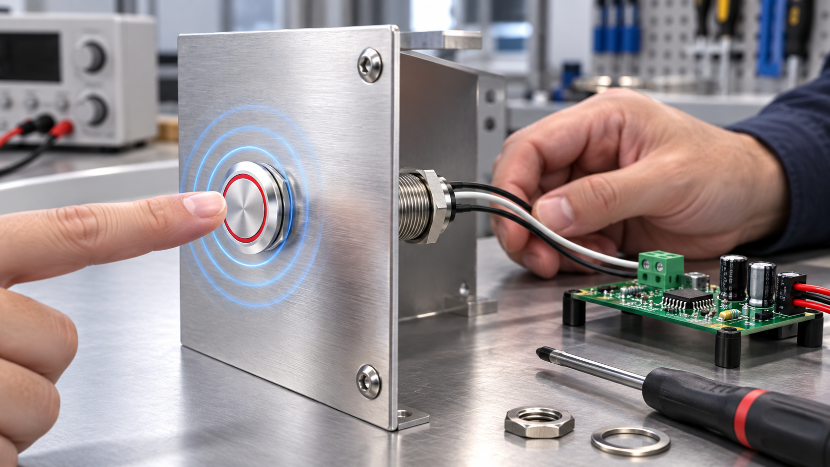
A capacitive touch switch circuit for a metal panel is not just a sensor connected to a button-shaped part. It is a complete sensing system: the touch electrode or metal surface, controller, wiring, reference ground, enclosure, and the user’s finger all affect the measured capacitance. A metal touch switch may use the front metal face itself as the sensing electrode, while a separate controller decides when a change is large enough to count as a touch. The exact circuit and output behavior depend on the selected product; do not infer terminal functions, voltage, isolation, or sensitivity from the front appearance.
This guide explains the circuit blocks and the engineering checks behind a metal-panel capacitive switch. It is not a wiring diagram for a particular ONPOW model. For model-specific connections, ratings, and installation details, use the current product documentation and confirm the complete assembly before release.
How a metal-panel capacitive touch circuit works
In a capacitive sensor, a controller observes a small change in the electrical relationship between an electrode and its surroundings. A finger near or on a conductive surface changes that relationship. The controller measures the change over time, applies filtering and a threshold, then changes a logic output when its detection rules are satisfied. A machine controller or relay interface may then use that output as an operator command.
The system therefore has at least two distinct functions: sensing touch and switching the machine circuit. A capacitive front end is not necessarily the same as a power contact. Some devices provide a low-voltage electronic output; others may package a controller and output stage into a product assembly. Only the exact circuit diagram can tell you which behavior applies.
Metal makes the electrode question especially important. A metal panel can be the intended sensing surface, can shield an electrode behind it, or can be part of a grounded chassis that changes the sensor reference. “Capacitive touch through metal” is not a universal property of every capacitive sensor. Texas Instruments describes a dedicated metal-touch approach in its CapTIvate technology guide, where the metal structure and its electrical reference are deliberately included in the sensing design. That is different from simply placing an ordinary sensor behind an arbitrary metal sheet.
Circuit blocks and what each one does
| Circuit block | Role in a metal-panel touch system | What the engineer must verify |
|---|---|---|
| Metal operator or electrode | Provides the surface whose capacitance changes near a finger | Whether the panel face is the electrode, an overlay, or a separate part; confirm material and mounting method |
| Sensor input | Connects the electrode to the sensing front end | Follow the exact pinout, cable, shield, and maximum lead arrangement in the controller documentation |
| Capacitance-measurement controller | Samples the sensor and estimates a baseline | Confirm supported electrode topology, calibration behavior, scan rate, and environmental limits |
| Threshold and filtering | Separates a genuine touch from noise and drift | Review debounce, hysteresis, baseline tracking, and fault behavior for the application |
| Output stage | Converts a touch decision into a machine-facing signal | Identify output type, polarity, load limits, isolation, and the receiving input requirements |
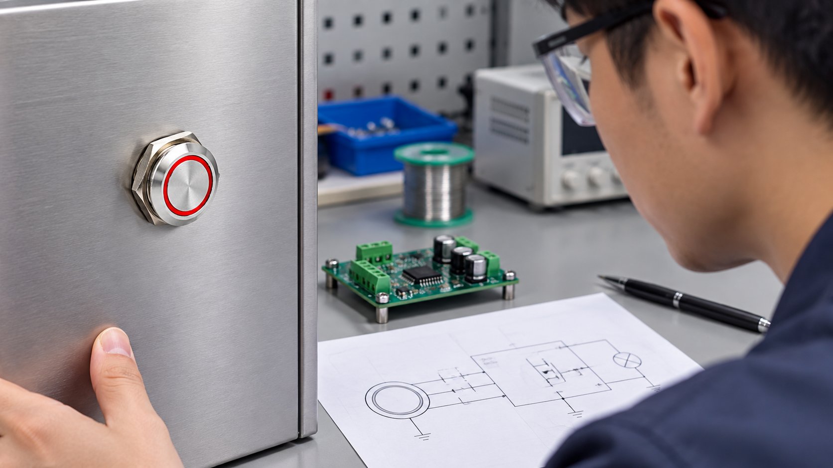
| Panel bond and reference | Defines the electrical environment around the sensor | Check chassis bonding, sensor reference, cable routing, and the intended ground scheme |
| Machine logic | Determines what the touch command does | Interlock the command as required; do not treat touch detection as a safety function by itself |
These blocks may be combined in a product or distributed across a sensor, controller board, and PLC. A product listing, image, or generic circuit sketch cannot establish how an exact model is internally connected.
What changes when the panel is metal
The front metal face can increase the effective electrode area and provide a robust, cleanable operator surface. It also makes mechanical and electrical integration more consequential. Panel thickness, cutout fit, insulating parts, nearby conductive structures, mounting hardware, and connection to chassis ground can change the field seen by the sensor. An assembly that works on an isolated bench plate may respond differently after it is installed next to a grounded door, cable shield, or machine frame.
There are different design architectures. In one, the front metal part is intentionally connected to a sensor input. In another, the controller detects a conductive overlay separated from the electrode. A third arrangement may use a metal frame or shield around a sensing area. These are not interchangeable. TI’s guidance for metal sensing treats the metal element and its reference as deliberate design variables; its general capacitive design guide separately discusses sensor layout, parasitics, grounding, and nearby materials. Use the appropriate manufacturer guidance for the controller architecture rather than copying a diagram from an unrelated product.
Do not assume that the metal front is electrically isolated from the output circuit, or that it is safe to connect it to protective earth, signal common, or a PLC input. That decision depends on the product design, the machine’s grounding architecture, applicable safety requirements, and the manufacturer’s instructions. Keep protective bonding, functional reference, and signal wiring distinct in the design review unless the approved documentation explicitly connects them.
A practical design and selection sequence
Start by stating the user action and the machine response. Is the touch a momentary request, a maintained state, an acknowledgement, or a navigation input? A touch sensor may have no tactile movement, so a visible or audible acknowledgement may be needed. Decide how the machine behaves during startup, a sensor fault, a controller reset, loss of power, and a stuck or continuously touched surface.
Next identify the exact product and circuit architecture. Record the ordering code, front-face material, mounting arrangement, rear connector or cable, supply requirement, output form, and any isolation details from the current drawing. If a datasheet does not answer a point, ask the supplier rather than guessing. A round stainless face alone does not prove that a part is capacitive, that it has a relay contact, or that it can directly switch a load.
Then validate the panel stack-up. Use the intended panel material, thickness, coating, mounting hardware, and nearby metalwork. If the sensing surface is mounted through a panel, check that the actual cutout and mechanical clamping do not introduce an undocumented insulating gap or short. If the panel is grounded, test the sensor in that exact grounding configuration. Do not add an insulating washer or connect a shield experimentally without checking the product instructions; either change can alter the sensing field.
Finally match the output to the control input. Confirm whether the touch module produces a digital logic level, open-collector output, relay contact, or another interface, and compare it with the PLC input’s voltage, current, polarity, common, and off-state behavior. Use an interposing interface if required by the design. A bare capacitive electrode is not a substitute for an appropriately rated machine-control output.
Commissioning checklist for a metal-panel installation
Test the complete assembly, not only a loose switch. Record the panel part number, touch-switch part number, controller configuration, supply, output type, cable routing, and ground/bond arrangement. Verify normal response using the intended operator’s bare finger and any expected gloves, then test realistic positions and approach angles. Confirm that nearby hands, cleaning cloths, vibration, and normal machine switching do not create false commands.
Test after the panel door is closed, after cable ties and covers are installed, and after the machine is grounded as it will be used. Check response during startup and after a power cycle. Confirm that the output goes to its designed state if the sensor cable is open, the controller reboots, or the system loses supply. These behaviors are product- and machine-specific; there is no universal fail-safe default for capacitive switches.
For a command that can initiate hazardous motion, validate it within the machine’s risk assessment and control system. A touch button should not be presumed to provide emergency-stop or safety-rated performance. The general comparison in ONPOW’s capacitive and piezoelectric switch analysis and the touch switch versus push button guide can help frame the interface decision; they do not replace the model’s approved documentation.
Common design mistakes
One frequent mistake is assuming every metal panel can act as an electrode. A sensor designed for a specific metal geometry may not behave the same behind a large grounded enclosure. Another is treating a product’s front appearance as evidence of the rear circuit. The terminal arrangement and output ratings must come from the model drawing.
Designers also sometimes choose a threshold on a clean bench and never repeat the test after final installation. Door bonding, cable routing, nearby switching supplies, coatings, water films, and a user’s gloves can alter the sensed signal. Do not compensate by raising sensitivity blindly: a lower threshold may increase false triggering, while a higher threshold may prevent intended users from operating the interface.
Finally, touch detection should not be allowed to ambiguously indicate that a machine action succeeded. The interface can acknowledge that a touch was detected, while a separate machine-state indicator confirms that the commanded function actually occurred. Make that distinction clear to operators.
Frequently asked questions
Does a capacitive touch switch work through any metal panel?
No. Metal may be the intended electrode or may shield a sensor, depending on the architecture. Confirm the controller and product documentation, then validate the real panel stack-up and ground arrangement.
Can a metal touch switch directly control a motor?
Do not assume so. The sensor output may be a low-voltage electronic signal rather than a load-rated contact. Check the exact output rating and use a properly selected interface when the load requires it.
Should the metal front be connected to earth ground?
Only according to the product instructions and the machine’s approved bonding design. Protective bonding, sensor reference, and signal common serve different purposes and should not be connected by guesswork.
Is a touch switch suitable as an emergency stop?
Not by default. Safety-related functions require a design that meets the applicable machine risk assessment and standards. A capacitive user interface should not be represented as safety-rated without evidence for the exact device and system.
How do I reduce false triggering on a metal panel?
Use the sensor manufacturer’s recommended electrode, reference, filtering, shielding, and cable layout. Commission the final grounded panel and validate the full operating environment rather than changing thresholds in isolation.
Educational video
The following Texas Instruments video demonstrates a dedicated capacitive-touch approach through metal. It is an explanation of a different sensing architecture, not a claim that every ONPOW touch switch has that capability.
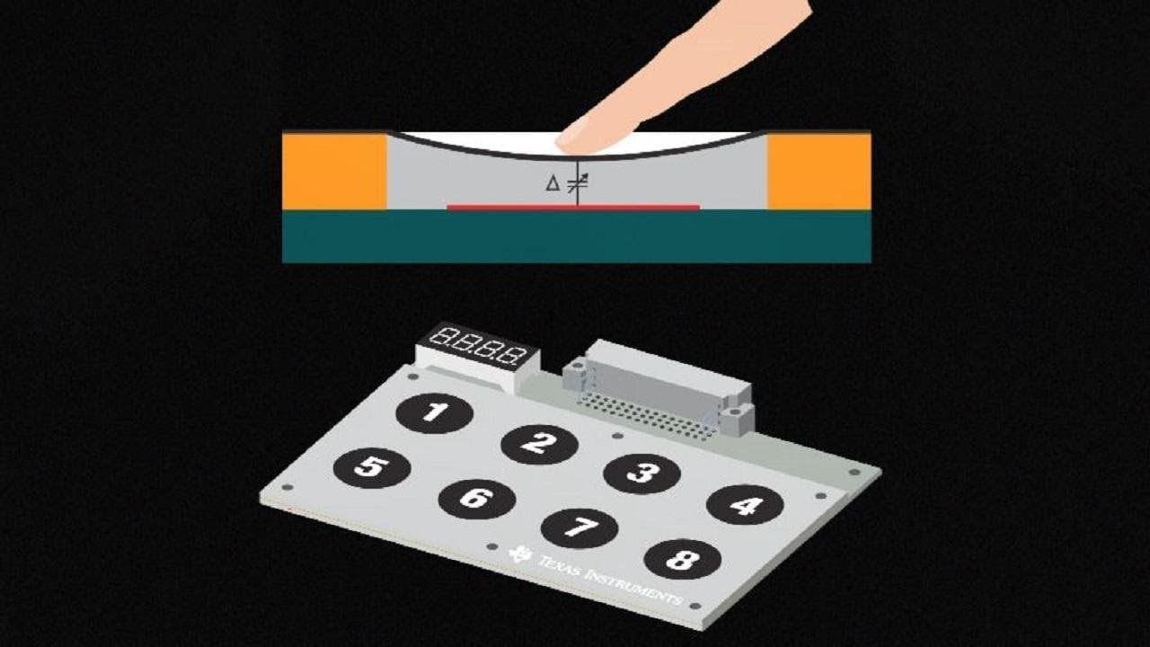
Watch the Texas Instruments metal-touch demonstration.
References
- Texas Instruments CapTIvate guide: metal touch sensing
- Texas Instruments CapTIvate design guide
- Microchip AN2934: Capacitive Touch Sensor Design Guide (PDF)
Related ONPOW products and guides
For a model-specific interface, review the TS19A metal touch switch and TS22D metal touch switch product pages, then confirm the exact order code and connection drawing with ONPOW. Continue with the related guides on touch sensitivity through glass and plastic and capacitive-switch false triggering for adjacent integration questions.



