

If an industrial buzzer does not sound, troubleshoot the complete control path before replacing the sounder: verify the selected model and supply, the controller command, the output module, the buzzer terminals, and the return path. A silent panel buzzer can be caused by an absent supply, incompatible sourcing/sinking output, incorrect common connection, wrong sounder variant, a loose terminal, or a failed device. One symptom does not identify which part has failed.
Start with the wiring diagram for the exact order code. For example, ONPOW’s GQ19B-M buzzer page lists product-specific supply and sound data; those details are not universal to every panel sounder. The buzzer product range includes other styles and configurations. This guide gives a safe diagnostic sequence for a control-panel buzzer, not permission to probe energized mains circuits.
Confirm what the selected buzzer should do
Before testing, record the full model code, supply version, sound pattern, terminal diagram, and the machine condition that should command the alarm. Similar cylindrical sounders may differ internally. Some are complete active buzzers that generate a tone when their specified supply is applied; other transducers need an external drive. Some assemblies combine an indicator light and sounder. A product photo alone does not reveal those electrical details.
Check whether the model should sound continuously, intermittently, or only as part of a light-and-sound pattern. If the part number is a continuous-sound version but the machine program expects an intermittent signal, the mismatch can look like a fault even though the buzzer operates as designed. Use the current product page and the manufacturer wiring diagram for the exact selected configuration. Do not substitute a pinout from a visually similar device.
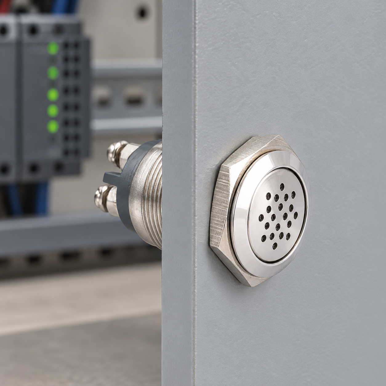
Trace the whole command and current path
Think of the alarm as a series of questions. Is the machine logic asking for a sound? Does the output module change state? Does the correct supply reach the buzzer input? Can current return through the expected common? Does the selected sounder respond when tested under the maker’s procedure?
Represent those points on a simple drawing before opening the cabinet:
| Check point | Nelerin doğrulanması gerekiyor | What a failed check suggests |
|---|---|---|
| Command condition | The machine state and alarm logic should request sound | The alarm condition, program branch, interlock, or acknowledgement state may not be active |
| Digital output | The output indicator/state changes when the command is made | Logic, output configuration, module fault, or output protection may be involved |
| Supply at the sounder circuit | The actual voltage and AC/DC type match the exact buzzer version | A missing, low, wrong-type, or interrupted supply may prevent operation |
| Output/load compatibility | Module output type, current limit, leakage, and common wiring fit the sounder | The module may not be able to drive the load directly, or the return path may be wrong |
| Sounder and terminals | Model code, terminal labels, polarity, and connections match the drawing | The device may be misidentified, disconnected, or faulty |
This is a fault-isolation table, not a universal pinout. The test point and measurement method depend on the voltage and panel design. Use a suitable meter and qualified personnel for any powered check. Never use a continuity setting on an energized circuit.
Check the controller output and common connection
Many industrial digital outputs are described as sourcing or sinking. A sourcing output supplies the positive potential to a load when active; a sinking output provides a path toward the reference return. The buzzer and its supply must connect in a way that completes the circuit for that output type. A controller output being “on” does not prove that the external device sees the correct voltage across its own terminals.
The NI guidance on industrial digital I/O connections explains sourcing and sinking in the context of specific output hardware. It is not a specification for an ONPOW buzzer or another PLC brand. Read the manual for the installed output module, including channel and group current limits, off-state leakage, output protection, external supply requirements, and common terminals.
If the output cannot supply the buzzer’s required current or switching type, the design may need an approved interposing relay or electronic driver. Confirm that interface device’s coil or input is compatible with the controller and that its contacts or output are rated for the sounder. Do not bridge output channels together or connect two supplies simply to make the buzzer sound during troubleshooting.

Follow a safe diagnostic order
- Review the approved drawing. Identify the buzzer model, supply, output module, protection, common, and intended alarm condition.
- Isolate before inspection. Follow the machine lockout and safe-isolation procedure before tightening a terminal, tracing a wire, or removing the buzzer.
- Check visual and mechanical conditions. Look for a loose plug or terminal, damaged cable, blocked sound opening, or an incorrectly seated panel unit. Do not dismantle a sealed sounder unless its instructions allow it.
- Check the control command. Observe the PLC or control output state using the documented diagnostic method. Confirm that an acknowledgement, timer, alarm silence, or interlock is not intentionally suppressing sound.
- Measure only at appropriate points. If a powered measurement is required, use correctly rated test equipment and competent personnel. Compare the reading at the output and buzzer terminals with the model and controller documentation.
- Separate the sounder from the logic. Where the manufacturer allows, perform a controlled functional test using the specified supply and protection, away from the machine’s hazardous motion. Do not improvise a bench voltage or polarity.
- Sonucu kaydet. Note the model, observed output state, measurements, sound pattern, and action taken. This makes intermittent faults easier to compare across shifts.
The Indian Government’s Bharat Skills Wireman training exercise demonstrates a simple buzzer-circuit fault check: verify the supply and trace the connections when no sound is produced. Its basic training circuit is not an industrial-panel wiring specification; apply the equipment-specific isolation and documentation required at the machine.
Distinguish an output problem from a sounder problem
If the controller never commands the output, investigate the alarm condition and logic. If the output indicates “on” but the buzzer has no valid supply across its terminals, inspect the output type, common, wiring, and protection. If the correct specified input reaches the sounder but it remains silent, check the product’s instructions for an approved standalone test or replace it with a known-good unit of the exact compatible version.
Intermittent sound may point to a loose terminal, an unstable supply, an intermittent output, a thermal/protection event, or an unsuitable sounder duty. Compare the fault with machine events and ambient conditions. Do not increase the alarm’s pulse rate or bypass the output protection as a diagnostic shortcut. The industrial buzzer selection guide covers supply, sound pattern, audibility, and environment; it complements this troubleshooting sequence rather than replacing the wiring diagram.
IEC 60204-1 covers electrical equipment of machinery, from the machine supply connection onward. The standard does not give a universal buzzer pinout or prescribe that a particular sounder alone constitutes a safety function. Use the machine’s risk assessment, approved alarm design, and applicable local requirements. If the alarm conveys a safety-critical warning, validate the complete signaling and response design with a qualified safety professional.
Common mistakes when a buzzer is silent
Replacing the buzzer first. Confirm the command, module output, correct supply, and return path before deciding that the sounder failed.
Assuming all two-wire buzzers are interchangeable. Voltage, AC/DC type, polarity, active/passive construction, terminal layout, and sound pattern vary by model.
Ignoring output leakage or module limits. Some controllers include diagnostics or protection circuits. Compare their off/on behavior and load limits with the buzzer documentation.
Using the wrong common. A missing, mismatched, or shared common can interrupt the current path even when an output LED appears to change state.
Testing by applying arbitrary voltage. A test supply that exceeds the rating or uses the wrong polarity can damage the device and create a hazard.
Treating an alarm silence or reset as a failure. Check the machine’s defined mute, acknowledge, latch, and reset behavior before changing wiring.
Educational video
This Engineering is Elementary (EiE) classroom lesson shows the current path in a simple alarm circuit with a buzzer. It can help visualize the supply, switch and sounder loop discussed above. It is a low-voltage learning example, not a wiring diagram for the ONPOW GQ19B-M or an industrial PLC.

Watch the basic buzzer alarm-circuit demonstration.
Frequently asked questions
Why would a new industrial buzzer stay silent?
Check whether the machine is commanding it, whether the output module is on, and whether the exact specified supply reaches the correct buzzer terminals with a complete return path. A new part can still be mismatched or miswired.
Does a PLC output LED prove the buzzer is receiving power?
No. The LED indicates an internal output state, but the external path still depends on the module output type, supply, common, wiring, and load compatibility.
Can I test the buzzer directly with a bench power supply?
Only if the manufacturer specifies a standalone test and the supply matches the exact model’s voltage, AC/DC type, polarity, and protection requirements. Otherwise use an approved diagnostic method.
What if the buzzer sounds but is too quiet or intermittent?
Check the sounder variant, supply under load, mounting, sound opening, alarm pattern, room noise, and controller duty. Compare the behavior with the model documentation and the intended alarm design.
Should I bypass the PLC or safety relay to prove the buzzer works?
Do not bypass a safety circuit or run a hazardous machine as an improvised test. Use an approved isolation and commissioning procedure with qualified personnel.
References
- IEC 60204-1: Safety of machinery — electrical equipment of machines
- National Instruments: Industrial digital I/O signal connections
- Bharat Skills: Wireman troubleshooting exercise for a buzzer circuit



