

A USB-C panel-mount connector should be qualified as part of the complete connection, including host, device, internal assembly and external cable. The reversible oval socket identifies a connector form; it does not by itself promise a data rate, USB Power Delivery, video output or every possible USB-C function. Specify the required task and confirm the supported roles and electrical paths for the exact assembly. Then test both plug orientations, the intended cable arrangement and the actual equipment. This approach prevents a physically convenient panel port from becoming an unreliable maintenance interface.
List the functions the machine actually needs
Start with a service-use statement. The port might exchange diagnostic data, connect a removable device or supply a permitted accessory. Do not combine these into a vague requirement for “full USB-C” without identifying which functions matter. A connector can satisfy one task while failing another, and the acceptance test must distinguish them.
Identify the host and peripheral equipment by model and interface documentation. Note whether either device can change its data or power role. The machine’s intended operating state matters: a connection used only during commissioning may have different access controls from one used during production. State who is authorised to connect and which external devices are approved.
The ONPOW USBC-01-(BK) product page provides a real panel-connector reference. Confirm the exact front and rear arrangement and available specifications with ONPOW. The photographs establish the physical product reference used here; they do not independently verify a power level, data rate, certification or environmental rating.
Keep connector form, data and power separate
USB-C is a connector and interface framework with capabilities that depend on the implementation. The USB-IF Type-C language guidelines help distinguish connector terminology from capability claims. Use the applicable equipment and assembly specifications to decide what the actual port supports.
A data connection needs the required signal paths through every segment. A power function needs the appropriate source, sink, cable and assembly capability. Video or another optional function introduces additional requirements. Do not infer any of these from the front receptacle alone or from a successful charge indication on an unrelated device.
A passive panel assembly also does not automatically add a controller, negotiate a new power function or convert a legacy interface into a different protocol. Identify whether the selected assembly includes active electronics. If the design relies on an active function, request its documentation and qualification evidence explicitly.
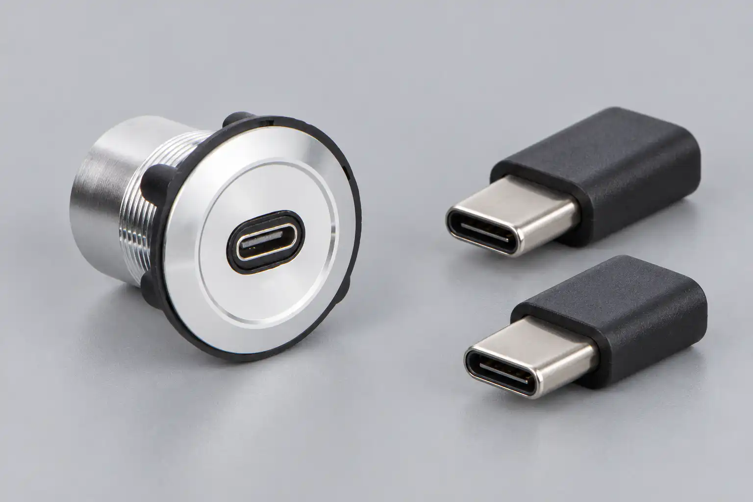
Draw every connection and role
Create a connection diagram showing the equipment port, internal cable, panel connector, external cable and intended device. Mark plug or receptacle at every interface. Include any adapter, coupler or internal extension that might otherwise be overlooked. A drawing makes incompatible assumptions visible before panel manufacturing starts.
Identify data roles separately from power roles where the equipment documentation requires that distinction. Do not assume that the device providing power must always be the data host. The complete system determines the supported arrangement. Keep the machine’s service instructions consistent with that arrangement.
For a legacy-interface comparison, the panel-mount USB selection guide explains the broader service-access planning process. USB-C qualification adds role, orientation and capability questions to that same end-to-end approach. It should not be treated as a simple change in socket shape.
Write a capability matrix for the exact assembly
Use a matrix to separate requirements from verified results. Leave unsupported functions explicitly unclaimed. The table below is an enquiry framework, not a declaration of capabilities for the referenced ONPOW product.
| Requirement | What the supplier should identify | What the acceptance test should demonstrate |
|---|---|---|
| Required data task | Supported path and assembly configuration | Actual application succeeds through final cables |
| Required power function | Permitted roles and assembly limitations | Intended equipment operates within approved conditions |
| Plug orientation | Supported connection arrangement | Required function works in both intended orientations |
| Optional video function | Explicit support and applicable configuration | Actual display task works if it is required |
| Mechanical installation | Drawing, mounting stack and rear clearance | Finished-panel fit and maintainable cable routing |
| Environmental condition | Applicable open, capped or connected state | Installation matches the verified condition |
| Replacement | Controlled order code and cable identity | Substitute matches the approved capability matrix |
Treat cable choice as part of the design
Specify the external cable rather than allowing any cable that happens to fit. Different cables can support different functions, and a convenient charging cable may not perform the required maintenance data task. Keep the approved cable identity with the machine documentation and test record.
Include the internal segment in the same review. A short panel adapter can still introduce additional interfaces and routing constraints. Do not assess only the external cable while assuming the internal connection is ideal. Qualify the total assembly at the final route and length, with the actual host and device.
The USB-IF compliance information provides the relevant programme and specification context. A supplier’s claim should identify the actual product and applicable programme where certification is claimed. Avoid describing an unverified cable or assembly as certified merely because it uses a familiar connector.
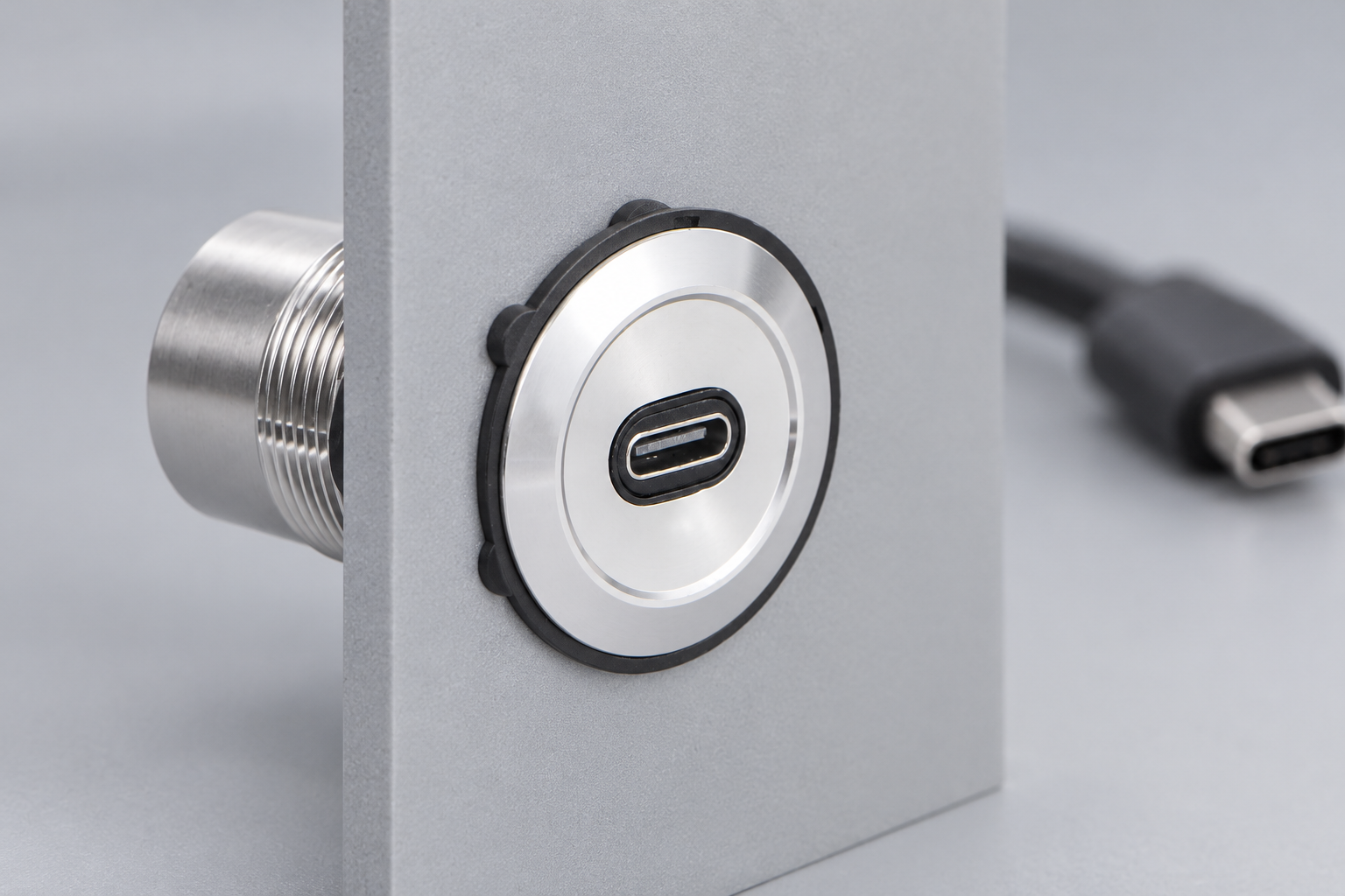
Check both orientations without changing the task
Use the same host, device, application and cable set when comparing plug orientations. Record which physical interface is reversed and the result for the required task. If the assembly contains more than one reversible connection, define the combinations that the qualification needs to cover. Avoid assuming one successful arrangement proves every arrangement.
A failure in one orientation is a reason to investigate the complete path, not a reason to tell technicians to mark the cable and always use one side. Confirm the intended design and supplier requirements. Preserve the failing configuration and record the symptom so the supplier can reproduce it.
Check recovery after an authorised disconnect and reconnect. Record whether the application resumes as intended or requires a documented recovery sequence. The machine’s service process should be robust enough for normal use, including the expected state of the equipment during connection.
Plan mounting, strain and enclosure protection
Use the exact mechanical drawing to define the cutout, finished panel thickness, gasket and retaining arrangement. Reserve rear clearance for connectors and cable bends. A port that fits through the hole but cannot be connected without forcing the internal cable is not a complete mechanical solution.
Prevent normal cable handling from loading the host equipment’s internal port. Follow the assembly’s installation instructions for support and strain management. Do not add a clamp that crushes the cable or place the cable across a sharp edge. Check access with the actual maintenance tools and panel-door movement.
Review the wider control-panel layout so the service interface does not obscure commands or encourage accidental operation. Environmental protection must be assessed for the exact open, capped and connected conditions; a metal bezel alone does not establish enclosure protection.
Include access control and clear labelling
An external USB-C port may look like a general charging outlet. Label the approved purpose clearly and state any restriction on connected devices. Align the physical label with the controller configuration and maintenance instructions. A label cannot enforce access control, but ambiguous labelling makes misuse more likely.
The equipment owner should define removable-media handling, authorised software and maintenance access. NIST’s operational-technology security guide provides broader system guidance. It is not a connector approval and should not be presented as one.
Keep this data interface distinct from a push button harness connector. Both can reduce maintenance effort, but they carry different signals and require different qualification evidence. Matching the word “connector” is not enough to establish electrical equivalence.
Run a documented qualification before production release
Build a representative panel with the final connector and internal assembly. Record the supplier code, drawing revision, equipment versions, cable identities and required functions. Check mechanical fit before energising or connecting the intended equipment under the approved procedure.
Run the real maintenance task through the complete path. Record both successful and failed attempts, orientation, equipment state and any error messages. If the task includes data transfer, check the application result rather than relying only on a connection icon. If it includes power, use the approved electrical test arrangement and acceptance limits.
Save the evidence with the bill of materials and replacement instructions. A later cable, controller or connector change can affect the qualified path even when the front socket still looks the same. Ask ONPOW to confirm the exact configuration against your connection diagram and capability matrix before ordering the production batch.
Frequently asked questions
Does every USB-C port provide the same data speed?
No. Confirm the required capability of the complete equipment, cable and panel assembly. Connector shape alone is insufficient.
Does a panel feedthrough automatically support USB Power Delivery?
No. The required roles, signalling and electrical capability must be supported by the complete system and explicitly verified.
Why should both plug orientations be checked?
The intended reversible connection should perform the required task in its supported orientations. Testing exposes assembly or compatibility problems that a single connection may miss.
Can a charging cable be used for maintenance data?
Only if its documented capability and the complete system test support that task. A cable that supplies power has not thereby demonstrated the required data function.
Further learning
University background on the USB host and storage-device relationship. This older foundational lecture does not establish USB-C power, orientation or optional-function requirements; use current USB-IF specifications for those checks.



