

A DPDT key switch operates two electrically separate changeover poles from one keyed actuator. Each pole has a common contact that transfers between two throws, so the complete device normally requires a verified six-terminal contact arrangement. In industrial control, this can authorize two coordinated low-voltage signals, provide complementary controller inputs, or change two independent control paths together. It must not be wired from a generic internet picture: identify both poles, both commons, every throw, the maintained or spring-return action, and the exact key-removal position from the manufacturer’s diagram and a de-energized continuity test.
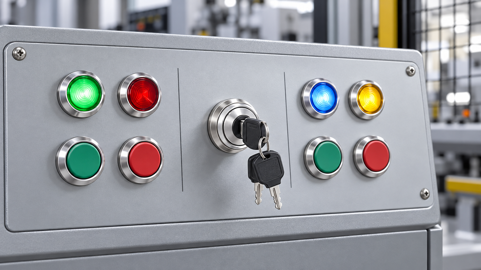
DPDT means two poles and two throws
“Double pole” means the mechanism switches two independent circuits. “Double throw” means each pole transfers its common between two possible outputs. The two poles move together mechanically, but they remain electrically isolated unless the designer intentionally connects them elsewhere.
For a true DPDT transfer function, label the circuits conceptually as Pole A and Pole B. Each has COM, Throw 1, and Throw 2. The labels printed on an actual product may be different, and a contact-block assembly may use manufacturer-specific numbering. Never assign numbers from the physical layout alone.
A key-operated head adds access control to that contact function. It does not change the basic DPDT topology, and it does not automatically make the device a safety switch, disconnect, or security system. The key limits casual actuation only to the extent defined by the key code, removal rules, operating procedure, and availability of duplicate keys.
Build a six-terminal truth table first
The following is an illustrative two-position DPDT requirement. It is not a wiring diagram for a specific ONPOW order code. It shows the information a designer should establish before selecting terminals.
| Key position | Pole A state | Pole B state | Example control purpose | Verification evidence |
|---|---|---|---|---|
| Position 1 | A-COM connected to A-1; A-2 open | B-COM connected to B-1; B-2 open | Enable local command and local status path | Manufacturer contact chart plus continuity result |
| Position 2 | A-COM connected to A-2; A-1 open | B-COM connected to B-2; B-1 open | Enable remote command and remote status path | Manufacturer contact chart plus continuity result |
The names “local” and “remote” are only an example. Other systems may use service/run, manual/automatic, or two mutually exclusive control sources. Define the real machine function and then assign the pole states. If one pole is used for command and the other for feedback, the feedback is still mechanically derived from the same operator; it is not automatically independent diagnostic proof of the controlled equipment’s state.
Document the normal reference position, whether the action is maintained or returns by spring, and which positions allow key removal. If the switch has a center position, it is no longer described completely by the two-row table above; use a row for every mechanical position.
DPDT is not the same as 2NO2NC
This distinction prevents many purchasing errors. “2NO2NC” states that the assembly has two normally open and two normally closed contacts. “DPDT” states that there are two changeover poles, each with a common that transfers between two throws. An assembly can present four independent contact elements without exposing the two common terminals required for a conventional six-terminal DPDT transfer circuit.
The official ONPOW LAS0-K30 catalog lists several contact structures for the key-switch family, including 2NO2NC and larger NO/NC combinations. That confirms that multi-contact versions exist in the family, but it does ليس by itself prove a six-terminal DPDT transfer arrangement. Request the exact terminal/contact diagram for the proposed order code and compare it with the required truth table.
If the application truly needs two changeover poles, write “two electrically isolated changeover poles with accessible commons” in the RFQ. If it instead needs two NO plus two NC signals, state those signals explicitly. The wording removes ambiguity before a sample is built.
Appropriate two-circuit uses
Complementary PLC inputs
One pole can command a mode while the second provides a complementary signal. The PLC can check for combinations that should never occur, such as both channels active. This can improve fault detection in ordinary controls, but any safety claim depends on the architecture, diagnostics, component data, standards, and validation of the complete safety function.
Switching two isolated control voltages
Separate poles can route two control circuits that must not be directly tied together. Confirm the product’s isolation, spacing, voltage, and environmental ratings from the exact datasheet. Do not assume that mechanical separation visible at the rear equals a specified electrical isolation rating.
Selecting paired command paths
The two poles can select coordinated paths, such as command plus indication supply. The loads still need to remain within the contact rating for the actual load type. Solenoid and relay coils can produce inductive transients; suppression and interface design should follow the load and controller documentation.
Reversing polarity
A DPDT topology can be arranged to reverse DC polarity, which is why many search results show motors and actuators. That application can create high inrush, arcing, dynamic braking effects, or unsafe motion. A small keyed selector should not be used as a direct motor-reversing device unless the exact product ratings and system design expressly permit it. In industrial equipment, the switch often commands interlocked relays, contactors, or a controller instead of carrying motor current.
Identify contacts without guessing
Begin with the full order code and current manufacturer drawing. Confirm that the operator, contact module, key code, and accessories are the parts listed in the approved bill of materials. A similar front bezel can hide a different rear assembly.
With all energy isolated under the machine’s approved procedure, verify absence of voltage. OSHA’s lockout/tagout guidance explains that control-circuit devices such as selector switches are not energy-isolating devices. Use the actual disconnect and energy-control procedure rather than turning the key to an off-looking position.
Set a continuity tester to the appropriate low-energy mode. Identify one common from the drawing, then check its two throws in each key position. Repeat for the second pole. Record results instead of relying on memory. Check for unintended continuity between Pole A and Pole B. Return the switch through every position several times and observe spring-return action separately from electrical continuity.
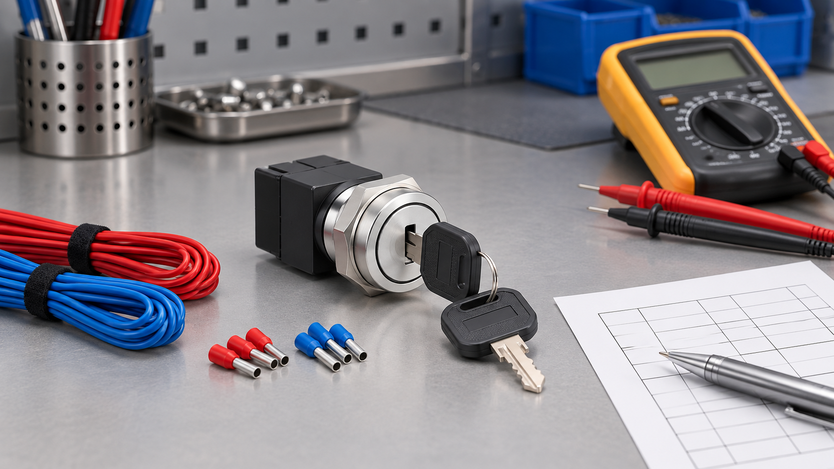
Do not probe or megger the product using a test voltage outside its documentation. A handheld continuity test confirms static open/closed behavior; it does not establish contact timing, dielectric performance, load endurance, or safety integrity.
Plan the panel wiring
Keep the two poles easy to trace. Use wire numbers or approved markers that match the schematic, separate circuits as required by the applicable design rules, and route conductors so door movement cannot pull on the terminals. Provide slack and strain relief without leaving loops that can foul moving hardware.
Ferrules and terminals must match the conductor and manufacturer instructions. Tightening torque, strip length, wire range, and terminal protection come from the exact product documentation. If those values are not available, request them rather than creating a generic assembly instruction.
At the controller, name inputs by function—for example, MODE_LOCAL و MODE_REMOTE—rather than only by terminal number. The schematic should still show the physical pole and terminal mapping. Software should define what happens when neither input or an impossible combination is detected.

Contact ratings and load interface
The contact rating must match voltage, current, load type, duty, switching frequency, and expected electrical life. A value stated for a resistive load cannot be applied automatically to an inductive coil, lamp inrush, capacitive input, or motor. DC switching can be more demanding because the arc lacks the natural current zero of AC.
When the switch feeds a PLC input, confirm input current and leakage behavior. When it drives a relay or contactor coil, review inrush and suppression. When it selects two different supplies, examine fault paths and isolation. If the load is beyond the contact’s documented capability, use the key switch as a low-energy command device and let a correctly selected interface component switch the load.
The applicable control-device product standard and the complete machine or panel standard should be identified by the responsible engineer. IEC 60947-5-1 covers electromechanical control-circuit devices and switching elements within its scope, but compliance and application details must be checked for the exact product and target market.
أخطاء شائعة
Counting rear tabs and calling the result DPDT
Terminal count is a clue, not a verified function. Accessories, lamps, separate NO/NC blocks, or duplicated tabs can change what is visible. Use the manufacturer diagram and continuity record.
Bridging the commons unintentionally
Joining the two commons eliminates electrical independence. If the design intends a shared supply, show that bridge explicitly on the approved schematic. Otherwise keep the poles separate.
Copying a motor-reversing diagram
Online DPDT results often show direct polarity reversal. That circuit may be inappropriate for a keyed industrial selector, its contact rating, or the required interlocking. Design from the load and risk assessment.
Treating the second pole as guaranteed feedback
Both poles share a mechanism. The second pole can provide another signal, but it does not prove that a contactor, valve, drive, or machine mode actually responded. Use feedback from the controlled device when the function requires it.
Using the key position as isolation
An “off” legend is a control command. It is not evidence that hazardous energy has been physically isolated.
RFQ and commissioning checklist
Provide the supplier with:
- A two-pole truth table for every key position.
- Maintained or spring-return action for each position.
- Required key-removal positions and key-code management.
- Control voltage, load type, steady current, inrush, and switching frequency.
- Required electrical separation and interface components.
- Panel cutout, thickness, anti-rotation feature, rear clearance, and enclosure conditions.
- The target standards, market, markings, documentation, and sample quantity.
- A request for the exact order code, contact diagram, terminal layout, ratings, and installation instructions.
During commissioning, compare the delivered assembly with that approved package, perform and record the de-energized continuity test, inspect conductor routing, and verify the complete machine response in every state—including power loss and restoration.
ال ONPOW key/selector switch range و ONPOW key-switch product page are the relevant product-family starting points. Review two-position maintained and return actions و three-position key-switch contact logic where those motions better match the application. The site’s DPDT versus SPDT guide provides broader topology context.
فيديو تعليمي
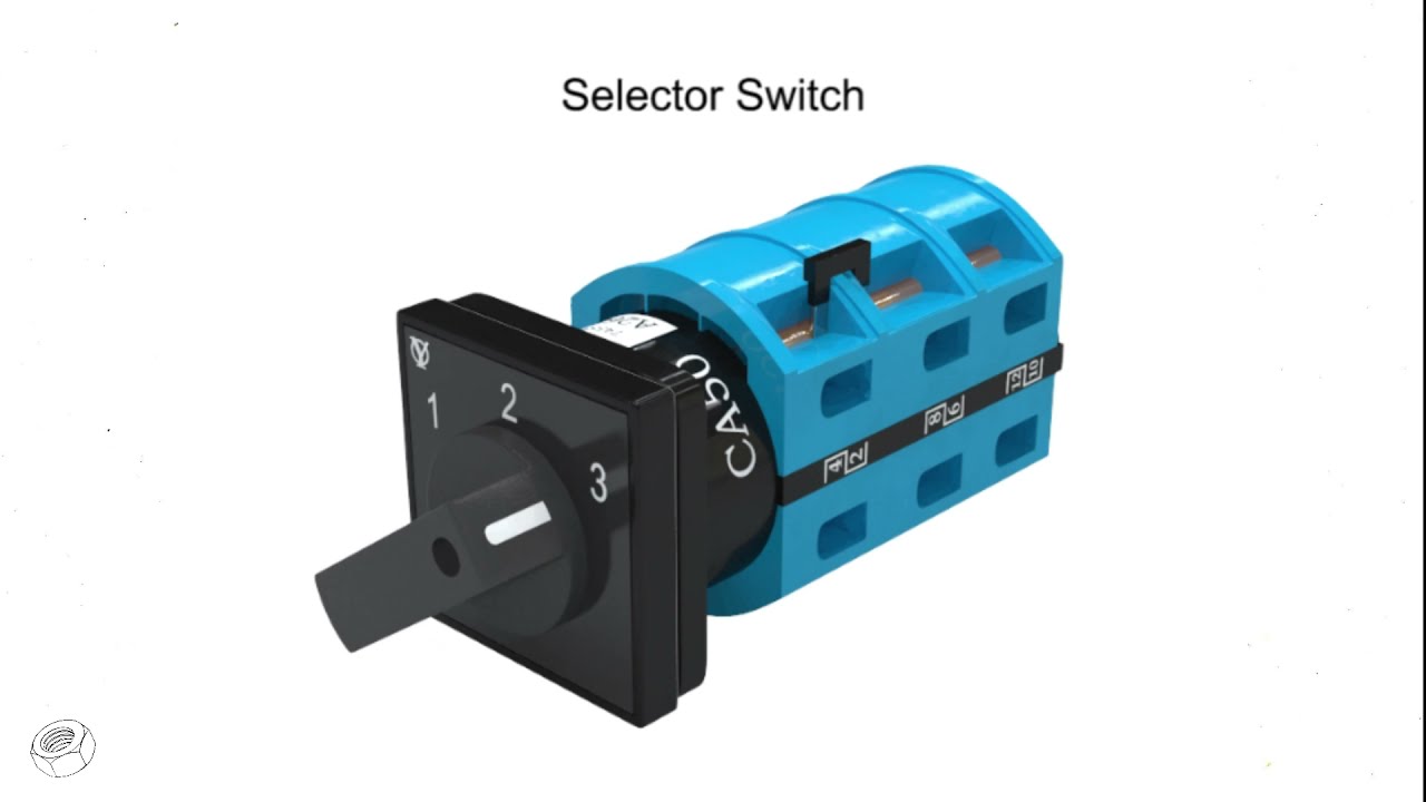
This neutral selector-switch animation helps visualize how one operator changes contact states. It does not establish DPDT terminals or ratings for a specific ONPOW order code.
الأسئلة الشائعة
How many terminals does a DPDT key switch have?
A conventional two-pole, two-throw transfer arrangement has six functional terminals: one common and two throws for each pole. Verify the actual product diagram because visible tabs and contact-block constructions vary.
Is 2NO2NC automatically DPDT?
No. The description identifies two normally open and two normally closed contacts, but it does not necessarily establish two accessible changeover commons. Obtain the contact diagram.
Can a DPDT key switch reverse a DC motor directly?
The topology can reverse polarity, but direct motor switching is acceptable only when the exact device ratings, inrush, arcing, motion risks, and interlocking have been engineered for it. Industrial selectors commonly command an interface device instead.
Can the second pole be used as a safety channel?
Not by assumption. Safety performance depends on the complete architecture, failure behavior, diagnostics, standards, and validation—not merely on having two poles.
القرار النهائي
Specify the required two-pole truth table first, then approve only an exact order code whose manufacturer diagram and ratings match it. Verify both poles with power isolated, keep circuit identity clear through the panel, and test the completed control response. To request a matched ONPOW configuration, send the truth table, load details, panel drawing, action type, and key-removal rule through the contact page.
Sources for verification: ONPOW LAS0-K30 catalog; IEC 60947-5-1:2024 scope; OSHA energy-control circuitry prohibition; Rockwell Automation selector-operator catalog.



