

A 2 position selector switch can provide a Hand–Off command when its documented contacts give the required closed state in Hand and open state in Off. Two handle positions alone do not identify the contact arrangement, terminal numbering, or load rating. Start with the exact order code and contact table, then decide whether the switch feeds a controller input or a properly selected relay circuit. This guide focuses on ordinary industrial mode selection, not power isolation or an emergency stop. The example logic is illustrative; the final machine schematic, risk assessment, and manufacturer documentation govern the actual connection.
Define what Hand and Off mean before choosing contacts
In a simple operator station, Hand means the operator requests a defined manual action. Off means that this selector does not request that action. Neither word describes every energy source in the machine. A pump may still have a separately supplied heater, a conveyor may retain stored pneumatic energy, and a controller may remain energized after its run request disappears. Document those distinctions in the machine description rather than relying on a label plate to convey them.
Consider an indoor transfer pump whose controller accepts a maintained manual-run request. A two-position operator might close one contact in Hand and open it in Off. The controller still needs to decide whether permissives allow the pump to run. Tank level, overload status, guarding conditions, and the machine’s stopping rules remain separate requirements. The selector is one input to that logic; it is not evidence that the complete installation is safe.
A different system may use a spring-return operator for a temporary command. That is a different behavior from a maintained Hand position even if both devices have two mechanical positions. Specify whether the handle stays where it is placed or returns after release. Do not substitute one action for the other during purchasing or replacement without evaluating the machine’s intended behavior.
Read the contact table rather than the handle photograph
A contact table relates each operator position to each contact pair. It should identify the view direction, operator action, installed contact blocks, and relevant terminal designations. Some assemblies provide one normally open contact, some a normally closed contact, and others several separate contacts. A drawing for the bare operator is insufficient if the order includes additional contact blocks or a different cam arrangement.
For a Hand–Off request, a useful starting requirement is a closed request path only in Hand. That requirement does not tell you which manufacturer’s terminals to use. Obtain the exact assembly diagram and translate its terminal references into the approved machine drawing. If a supplier provides only a photograph and a general family datasheet, request the missing contact table before releasing the order.
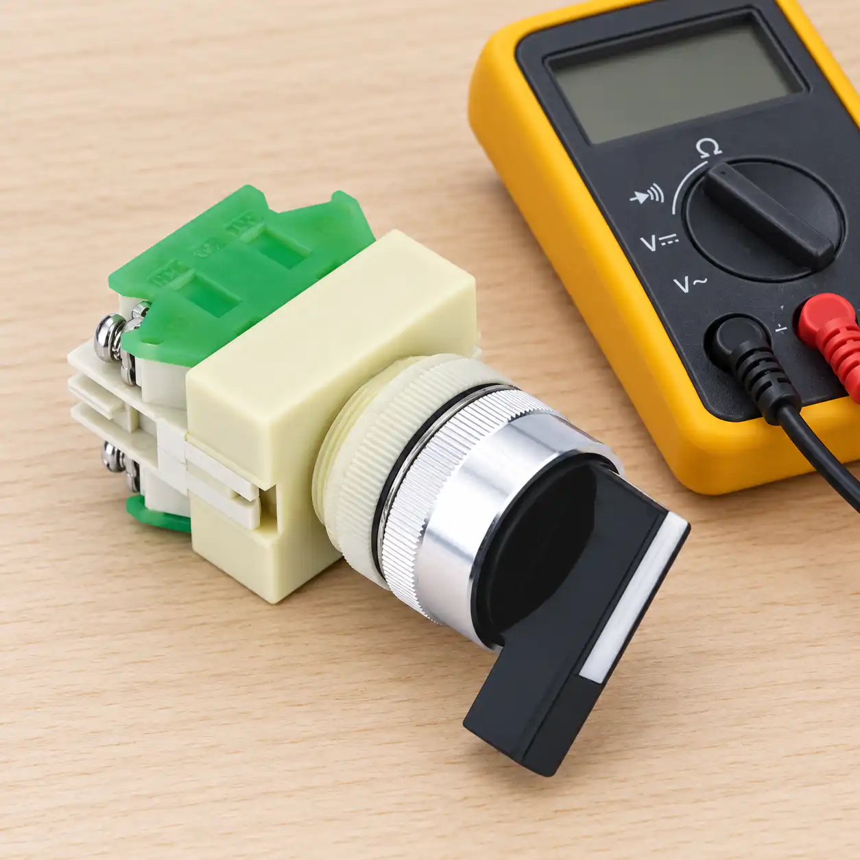
An independently isolated continuity check can corroborate the drawing. It cannot establish the permitted switching current, insulation performance, or safety suitability. Qualified personnel must follow the site’s isolation procedure and verify the equipment is de-energized before contact identification. The official 29 CFR 1910.333 electrical work practices distinguish control devices from the means needed to de-energize equipment. Applicable local requirements may differ.
An illustrative Hand–Off contact plan
The following table describes a design requirement for a manual-run request. It is not the terminal map of the illustrated ONPOW product and must not be used as a wiring diagram. A machine may require additional contacts, separate monitoring, or different logic.
| Condition | Request contact requirement | Controller interpretation | Verification point |
|---|---|---|---|
| Handle at Off | Manual request path open | No manual request from this selector | Confirm the command disappears and the approved stopping response occurs |
| Handle at Hand | Manual request path closed | Manual request present, subject to permissives | Confirm a request alone cannot defeat an interlock |
| Broken request conductor | Open circuit | Interpret according to the validated input design | Confirm the documented fault response; do not assume all faults are detected |
| Power returns while Hand is selected | Contact may still be closed | Apply the machine’s restart policy | Test restart prevention or required acknowledgement under the approved procedure |
This contact plan provides a concrete acceptance target without inventing a universal terminal number. If the machine requires a separate Off indication, assess a second contact or other appropriate feedback. One request contact cannot distinguish every possible open-circuit fault from an intentionally selected Off position.
Controller input or relay coil: choose the correct interface
A selector used as a controller input switches the input circuit rather than the motor current. Confirm the input voltage, common arrangement, required contact performance at low current, filtering, and wiring rules in the controller documentation. A dry contact does not create its own supply. The input module’s sinking or sourcing arrangement determines the permissible circuit, and the exact machine drawing must show that arrangement.
A selector driving a relay or contactor coil has a different load. Confirm the coil’s voltage, AC or DC designation, inrush or operating current where specified, duty, and switching category. A general current marking is not automatically an inductive-load rating. Coil suppression can also affect release behavior, so review it as part of the complete control circuit rather than adding a convenient part during commissioning.
For larger load circuits, frequent switching, or an interface requiring separation, the selector may need a relay or contactor selected for that role. This is a design choice, not a promise that every selector should operate every coil. The electromechanical relay wiring guide explains the distinction between coil and contact paths. Use the current datasheets for the specific switch, controller, and relay before deciding how they connect.
A control rating is different from an insulation marking
The ONPOW Y090-11XB/21 product page lists Ui and Ith values alongside mechanical, electrical, material, and front-panel protection information. Ui is an insulation-related designation, and Ith is a thermal-current designation. Neither should be interpreted as permission to switch every load at that voltage and current. Request the operational rating for the actual AC or DC circuit and applicable utilization category.
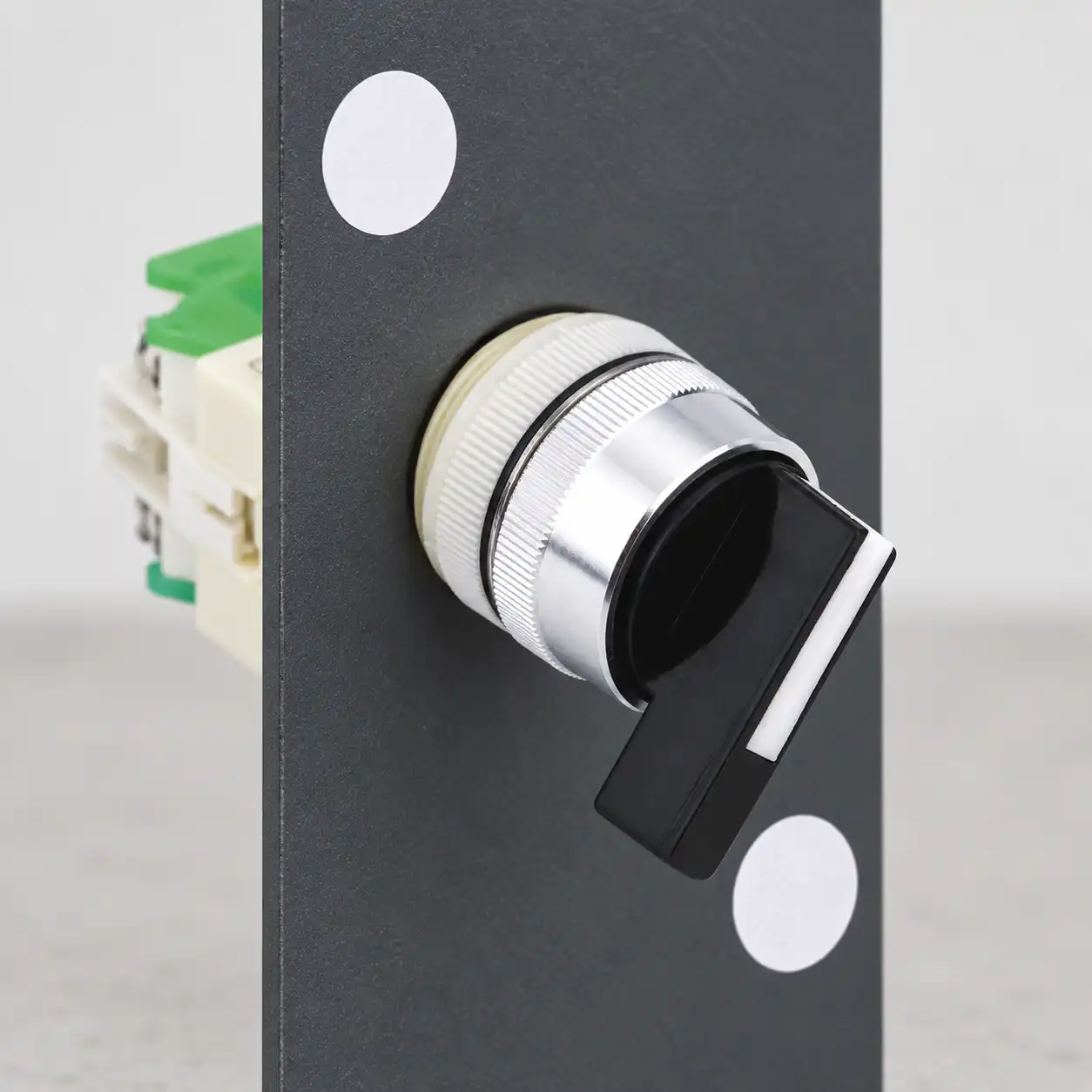
The public page also lists front-panel IP40 for this model. It does not establish suitability for outdoor exposure, direct washdown, or every installed enclosure. Confirm panel sealing, installation details, contamination, temperature, and the environment for the exact order. This article’s images show dry indoor inspection settings and do not illustrate a waterproof installation.
When reviewing a standard, separate its scope from a product’s declared conformity. IEC 60947-5-1 concerns electromechanical control-circuit devices. A link to that standard does not certify the illustrated product or the whole machine. Ask for the documentation applicable to the ordered device and the current requirements of the destination market.
Installation details that can change the intended command
The operator must be secure enough that the position label and handle direction remain meaningful. Check the panel cutout, allowed panel thickness, anti-rotation arrangement, mounting hardware, and the manufacturer’s tightening instructions. A device that twists in the panel can make a correct electrical command appear to be a different mode to the operator.
At the rear of the panel, confirm contact blocks are properly retained and terminals have sufficient access. Route conductors so opening the enclosure does not pull on the switch. Choose conductor preparation and connection methods from the terminal documentation. Do not infer screw torque, wire size, or connector compatibility from a picture of another selector in the same family.
Use durable labels that describe the machine’s function. If Hand operates a pump, label the function consistently in the control drawing, operator instructions, and controller display. Avoid a generic On label where the selector merely grants a permission and a separate command starts the equipment. Clear wording reduces the chance of a technician interpreting a permission signal as confirmation of motion.
Commission the request and the machine response separately
First confirm the isolated contact state against the approved table. Then check the input or coil circuit under the site’s controlled commissioning procedure. Finally confirm the actual machine response, including permissives and required stopping behavior. Passing the first check does not demonstrate that the controller interprets the signal correctly or that the final load stops as required.
Test the transitions that matter to the application: Off to Hand, Hand to Off, a missing permissive while Hand remains selected, and restoration of that permissive. Also evaluate power interruption and power restoration under the approved restart policy. Keep personnel outside hazardous areas and use the required safeguarding and supervision for those tests.
Record expected and observed behavior for each test. If the request is present but the equipment does not operate, investigate the controller logic and permissive chain before bypassing anything. If the equipment runs in Off, treat the discrepancy as a commissioning failure and trace the approved circuit. The switch debouncing guide provides related background on input transitions; filtering must not conceal an incorrect contact arrangement.
Information to send with a selector inquiry
Provide the intended Hand–Off function, maintained or spring-return action, required contact table, control supply, connected load, panel drawing, environmental conditions, labeling, and destination requirements. Ask the supplier to confirm the complete assembly order code and the appropriate rating rather than quoting only the knob size or a broad family number.
A procurement record should include the approved drawing revision and the acceptance checks. That makes a later replacement traceable and prevents an apparently identical handle from being accepted with the wrong contacts. Start with the broader selector switch types guide when comparing operator families, then send the actual application details through ONPOW’s contact page.
Vzdělávací video
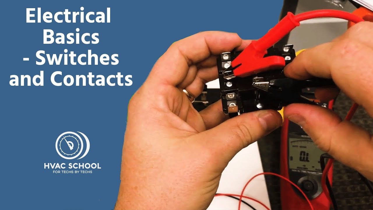
Electrical Basics – Switches and Contacts by HVAC School. General contact behavior; the exact selector diagram and machine design govern. Open the video on YouTube.
Často kladené otázky
Does a two-position selector always have one normally open contact?
No. Position count describes the operator. The installed contact blocks and cam determine the electrical arrangement. Obtain the contact table for the complete order code.
Does Off isolate the machine for maintenance?
Not by itself. Off can remove a control request while other energy sources remain present. Use the required isolation and verification procedure for the equipment.
Can the selector switch a motor directly?
Only if the exact documented rating and application requirements permit it. Many mode-selection circuits operate a controller input or relay coil instead of carrying the motor current.
Will a maintained Hand position restart the machine after power returns?
It may leave a request present. The controller and machine design must implement and validate the required restart behavior; the handle alone does not decide it.
Can I identify the terminals from the product photo?
No. A photo helps identify the package, but the assembly diagram and terminal-view direction are needed to establish the contact map.



