

A normally open micro switch has an open contact path in its defined normal position; a normally closed micro switch has a closed path in that position. Actuating the switch changes the relevant path. Choose NO or NC from the signal the complete control circuit needs, including its response to broken wires, stuck contacts, and mechanical reset. NC can make some open-circuit faults visible, but NC alone does not make a circuit fail-safe. The manufacturer’s contact diagram defines the component state, while the equipment drawing and control logic define what that state means for the machine.
Normal refers to the switch, not the production process
The word normal usually refers to an unoperated actuator in a mechanical switch drawing. It does not necessarily describe the mechanism during routine machine operation. A switch under a stationary cam can be operated whenever the machine is in its home position. In that installation, the contact marked NO may be closed while the machine is ready.
Start by drawing the actual target positions: absent, arriving, fully present, leaving, and returned. For each position, record whether the actuator is operated. Then translate the contact state into the controller signal. Keeping those two descriptions separate prevents a maintenance technician from assuming that NC always means machine healthy.
A conventional SPDT switch may provide both NO and NC paths through a common connection. It is still one mechanical sensing arrangement. If only one path is used, record the unused terminal in the drawing and protect it according to the product’s installation instructions. Do not connect it simply because an extra terminal is available.
Compare the required signal, not an abstract preference
NO and NC are useful for different ordinary control tasks. NO can report the arrival of a target. NC can supply a continuing indication that disappears when an actuator operates or a conductor opens. Those are signal patterns, not universal instructions for every application.
| Decision point | An NO path may suit the purpose when | An NC path may suit the purpose when |
|---|---|---|
| Target detection | A closed contact should announce target arrival | Target arrival should interrupt a continuing signal |
| Cable-open observation | The system has another way to distinguish no target from cable failure | Loss of a continuing signal is an actionable condition |
| Mechanical home position | The target normally leaves the actuator unoperated | The actual normal mechanism can be mapped correctly to the chosen contact |
| Input logic | The input and program interpret closure as the intended event | The input and program interpret opening as the intended event |
| Protective function | The specified architecture permits the selected device | The specified architecture permits the selected device; NC by itself is insufficient |
The table is qualitative application planning. It does not assign safety capability, current ratings, or terminal numbers to any model. Use the micro switch working-principle guide for the mechanism and the micro switch versus limit-switch comparison for packaging and installation context.
Understand what an open wire can and cannot reveal
In a simple NO arrival circuit, an open cable may look the same as an absent target. The input stays inactive in both cases. Whether that ambiguity matters depends on the process and its other information. A machine might cross-check a second process event, use a timeout, or perform an approved diagnostic cycle. The appropriate method is defined by the equipment design.
In a simple NC monitoring circuit, an open cable can remove the continuing signal, creating a visible change. That is one reason designers sometimes choose NC for ordinary monitoring. However, the circuit still needs to decide whether signal loss means target operation, wiring failure, or another condition. A basic input does not necessarily tell those causes apart.
A short across the contact can defeat the expected interruption. A short to a supply or return can give a false state. A welded contact can remain closed. A failed controller input can display an incorrect condition independently of the field contact. List these faults explicitly instead of describing one contact choice as detecting every failure.
Keep safety-related sensing separate from ordinary feedback
A standard process-feedback micro switch is not automatically suitable for guard monitoring, emergency stopping, or another protective function. Relevant requirements may concern contact design, direct-opening action, device mounting, fault tolerance, diagnostics, and the response of the complete system. Selecting an NC terminal addresses only one part of that problem.
The IEC 60947-5-1 publication describes the scope of electromechanical control circuit devices. It does not establish that every component with an NC contact meets a machine’s required protective performance. Obtain the model-specific documentation and have the protective function designed and validated for the application.
Do not defeat an interlock while diagnosing a contact problem or substitute a conventional switch for a specified protective device solely because it fits. If the existing switch is part of a documented safety function, the replacement review must preserve the required capabilities and the equipment’s validation procedure.
Translate the mechanical state into the PLC input
A PLC may display an energized input when the contact closes, but the software can invert or combine that signal. The physical input state and the program’s meaning are separate. An HMI message reading limit reached may be generated from a contact opening, a contact closing, or a computed condition involving several inputs.
Document the field contact, wire numbers, input module, electrical common, program address, and intended message. Verify sourcing or sinking requirements and the permitted voltage and current from the input-module manual. A dry mechanical contact has no universal positive or negative wire; the surrounding circuit establishes those connections.
When changing from NO to NC or vice versa, review the program and sequence rather than only moving a conductor. The change may reverse the response to power loss, cable failure, or an actuator that fails to reset. Evaluate whether filtering, event timing, and alarms also depend on the original signal polarity.
Reset travel matters as much as contact selection
A correctly selected contact can remain in the wrong state if the actuator stays partly operated. A long lever can catch on the target, a plunger can receive side force, or a bracket can shift enough to prevent full release. This is a mechanical fault, not necessarily the result of choosing NO instead of NC.
Compare operating position, release position, permitted overtravel, and the target’s complete motion. Ensure there is a reliable reset path over the full range of alignment and wear expected in service. Do not force the actuator beyond its specified travel to make the meter show the desired state.
For the mechanical side of the selection, read micro switch roller and cam geometry. If a housed switch is being wired into a position-feedback circuit, the limit-switch NO/NC wiring guide covers that related application.
Test a state matrix instead of only listening for a click
Inspection or rewiring of installed equipment must follow the applicable energy-control procedure. Qualified personnel should account for stored energy and verify the electrical condition before accessing contacts. In the United States, 29 CFR 1910.147 and 29 CFR 1910.333 provide relevant hazardous-energy and electrical-work requirements.
A controlled isolated contact test can compare the defined normal position with the operated position. Record both the terminal pair and actuator position. Parallel paths can make a continuity result misleading, so use the equipment’s approved isolation and testing method. A click does not prove electrical continuity or the contact’s ability to switch its specified load.
After the approved return to service, verify physical target position, controller input, program interpretation, and machine response together. Include approach and release. Any diagnostic-fault test must be part of an approved plan; do not introduce cable faults into a running machine as an improvised experiment.
What to send the supplier when ordering
Send the existing part number and suffix, contact-state drawing, actuator type, mounting information, normal mechanical position, circuit voltage, load type, and receiving-input data. Explain whether the application needs an arrival signal, continuing indication, or another defined behavior. Include the required response when the signal is lost.
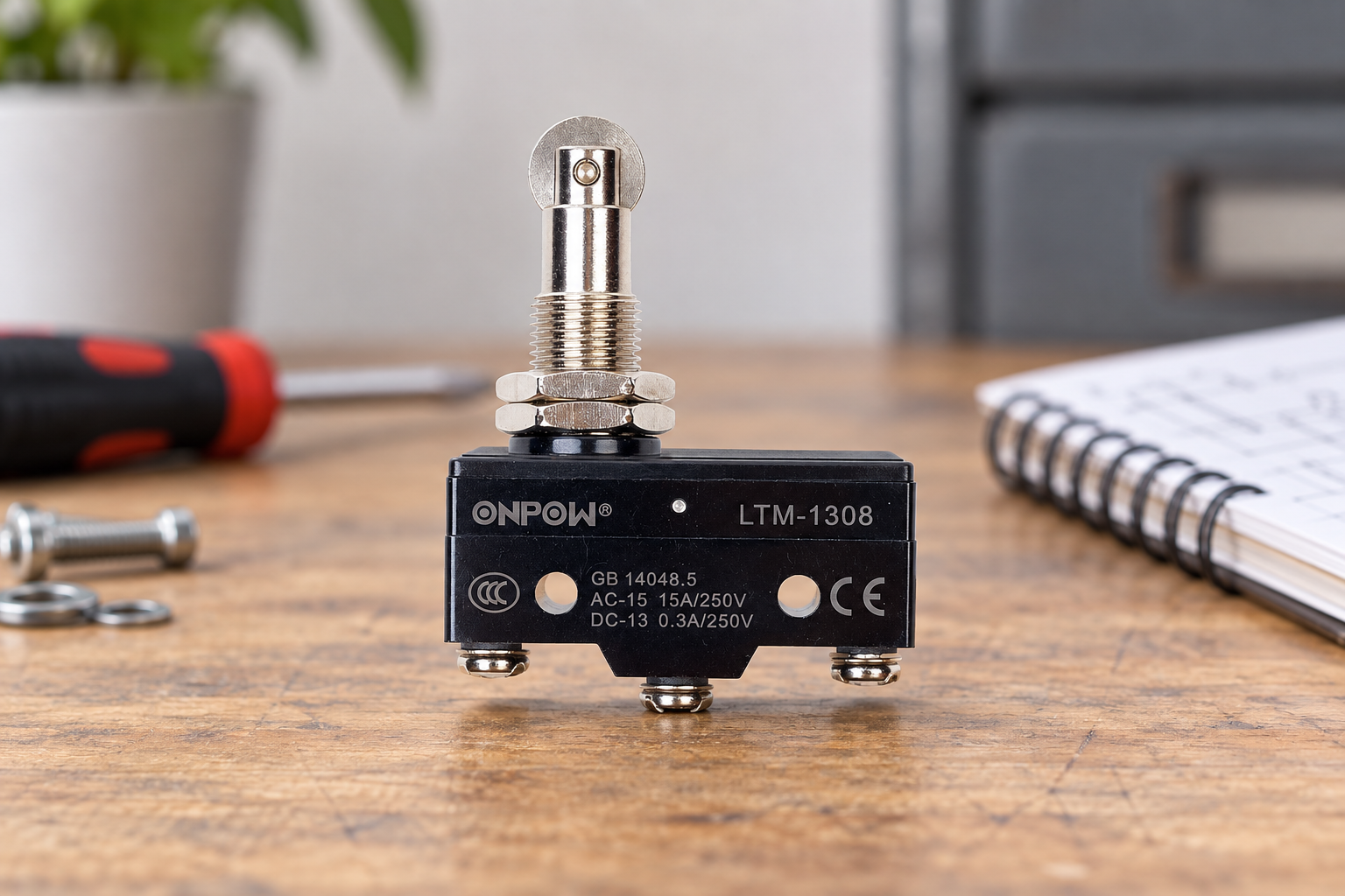
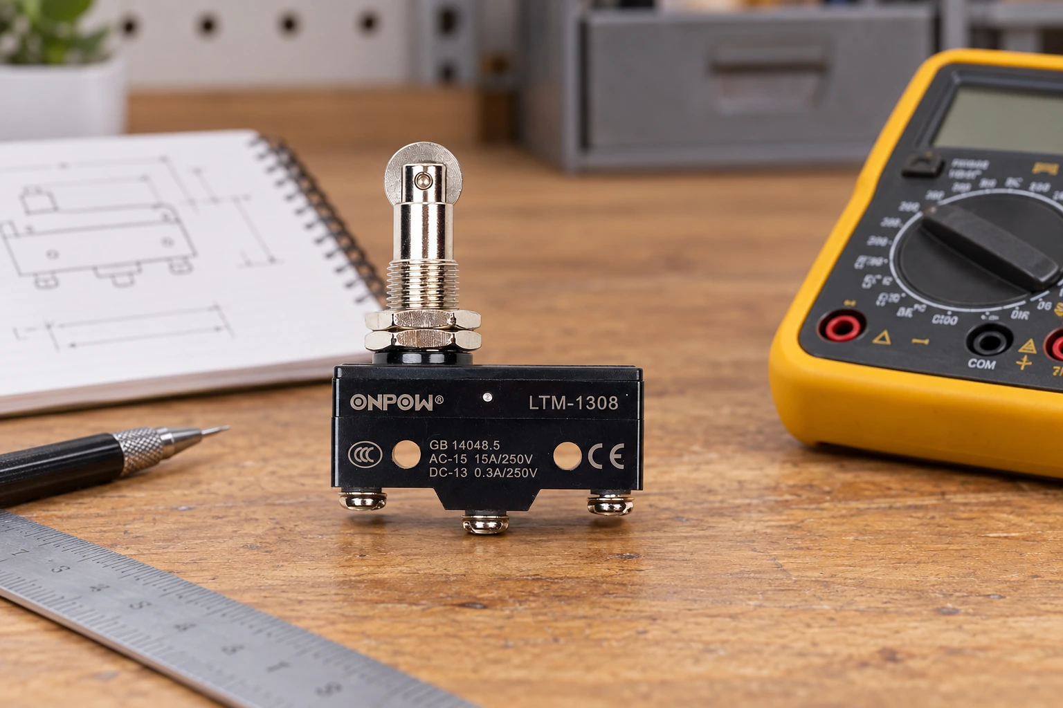
The ONPOW LTM-1308 product page is a real product reference for discussing the mechanical interface. Ask for the exact variant’s contact drawing and installation data. Product appearance is not proof of terminal identity, safety capability, or suitability for a particular PLC input.
For purchasing review, use the industrial micro switch selection checklist. Keep the approved contact choice in the wiring schedule so that a future replacement does not quietly reverse the process signal.
Vzdělávací video
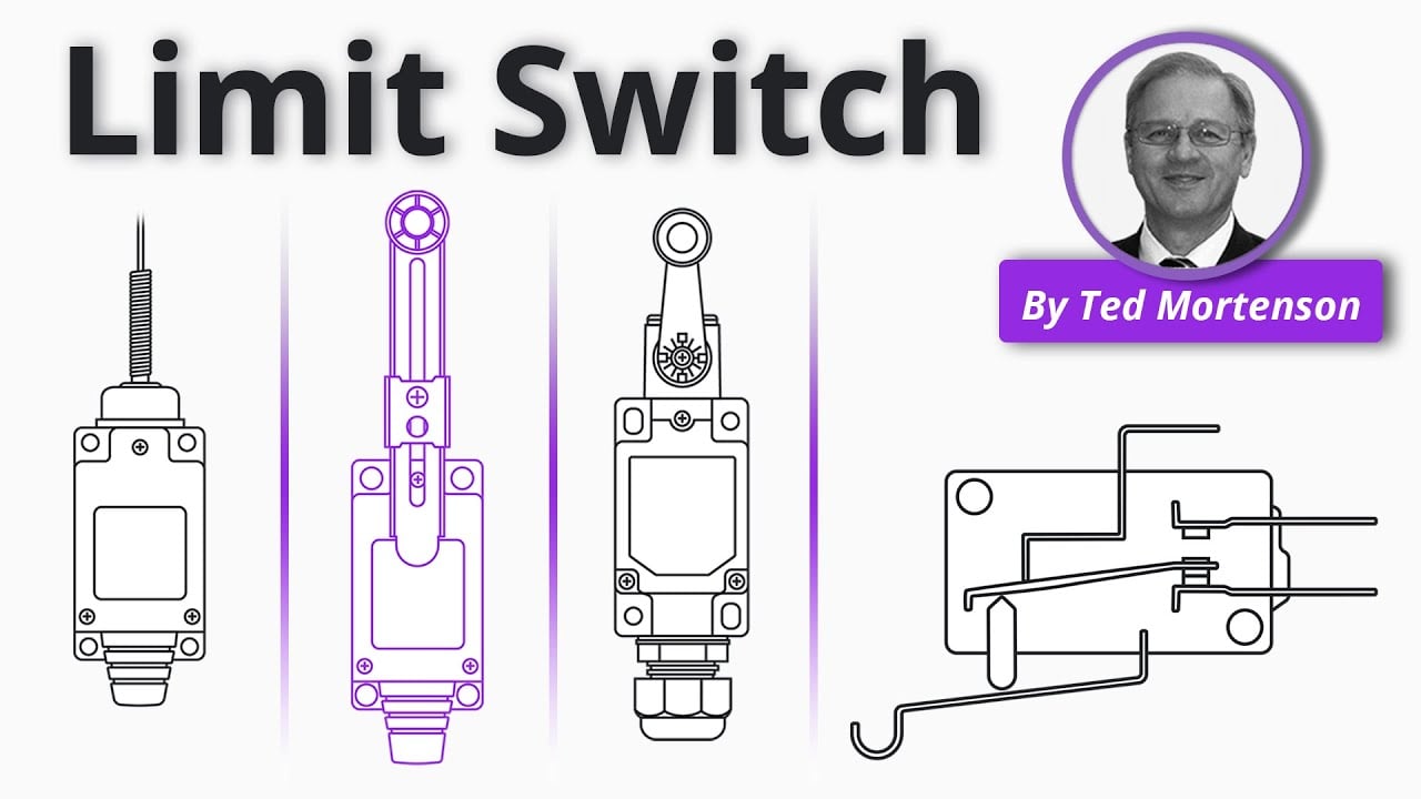
Limit Switch Explained | Working Principles by RealPars. General educational background. Use the selected product drawing and the machine design for the actual circuit and installation. Watch on YouTube.
Často kladené otázky
Is normally closed always safer than normally open?
No. NC can expose some open-circuit faults in certain arrangements, but safety depends on the complete function, suitable devices, diagnostics, and validation. NC alone is not a safety rating.
Can one SPDT micro switch provide both NO and NC?
A conventional SPDT version can provide both paths through a common contact. Confirm the exact drawing; the paths are not two independently actuated sensors.
Why is my NC contact open when the machine is at home?
The home mechanism may hold the actuator operated. NC refers to the switch’s defined normal position, not necessarily the machine’s home position.
Can software invert the signal instead of changing the wire?
Software can change the interpretation, but the resulting response to faults and power loss must still be reviewed. Use the equipment’s approved design and commissioning procedure.
Why does the input remain on after the target leaves?
Possible causes include insufficient release travel, a sticking actuator, wiring faults, contact damage, or incorrect program interpretation. Compare the complete state matrix before replacing the device.



