A push button connector should be specified as a complete mating interface, including the device, mating component, contacts, wiring assignment and assembly process. A plug that appears to fit is not automatically an approved match, and the same number of positions does not establish the same circuit arrangement. Start with the exact switch and connector codes, then obtain the mating drawing and harness requirements. This guide concerns the electrical and mechanical handoff between an industrial push button and its harness, not a universal pinout or a claim that every ONPOW model uses an interchangeable connector.
Define which parts the order must include
Separate the button assembly from the mating connection parts. A supplier may offer a switch alone, a switch with a connector feature, a mating housing, loose contacts or a preassembled harness. These are different deliverables even when they appear on a page with the same product photograph. State explicitly what the equipment builder expects to receive.
Identify whether the connection is intended to be detachable during service or only during a controlled assembly operation. Include the available installation and removal access. The practical value of a connector depends on whether the equipment permits its intended use after the panel is fully assembled.
The existing push button with connector overview introduces the general product category. Here the focus is the narrower qualification task: establishing that the complete mating interface is documented, correctly wired and suitable for the actual assembly process.
Obtain exact codes and controlled drawings
Record the device code and revision, connector family, mating housing, contact parts and any required accessory. Do not use a family name or position count as the complete specification. Within a family, alternatives can differ in keying, contact construction, wire acceptance or the part of the assembly that provides retention.
Request a drawing that makes the mating relationship unambiguous. It should identify the relevant views and the actual parts included. A front photograph of the operator cannot establish the rear connector arrangement, and a drawing of an empty housing cannot establish the permitted contact and conductor combination.
Keep the drawing revision with the harness record. A service team needs to know which configuration was installed, not merely which catalogue was available when the equipment was built. Supplier statements about compatibility should identify the exact parts rather than relying on an informal assurance that they are “the same type.”
Distinguish keying, orientation and position identity
Mechanical features can help prevent an unintended mating orientation, but their presence is not proof that every visually similar part belongs to the same system. Confirm the intended keying and engagement arrangement from the manufacturer information. Do not remove or reshape a feature to make a candidate plug fit.
Read position identifiers from the specified view. A contact face, wire-entry face and drawing of the mating half can look mirrored. State which view is used in the harness document and preserve that convention during inspection. A correctly assembled housing can still contain an incorrect circuit assignment.
Avoid identifying a position only by “left” or “top” without a reference orientation. Include the manufacturer’s position designation and a clear controlled view. This is particularly important when the switch is rotated during panel installation or inspected from the rear of an open door.
Use an interface qualification table
The table is a qualitative review tool. It does not supply a terminal sequence, allowable conductor range or connection rating. Obtain those values and requirements for the exact ordered interface before manufacturing the harness.
| Interface question | Required evidence | Shortcut to avoid |
|---|---|---|
| What is supplied? | Itemized device, housing, contacts and harness scope | Assuming a photograph represents the full kit |
| What mates together? | Exact approved component combination | Selecting by appearance or position count |
| How is orientation controlled? | Keying and reference-view drawing | Forcing or modifying the mating feature |
| Which circuit reaches each position? | Controlled device-to-harness assignment | Transferring wire colors from another model |
| How are wires terminated? | Permitted conductor, contact and process instructions | Using an unqualified crimp or solder process |
| How is the assembly retained? | Specified engagement and inspection method | Treating physical insertion as complete proof |
| How is it serviced? | Safe removal access and replacement procedure | Pulling on conductors to release the plug |
Resolve missing entries before approving production. A successful informal connection on a desk cannot establish the whole interface, especially where the finished equipment changes access, wire routing or environmental exposure.
Map contacts and illumination separately
An illuminated push button can combine switching and indication circuits in a model-specific arrangement. Identify each required function from the exact diagram before assigning harness positions. Do not assume that every connector position is a switching contact or that a common point means the negative supply.
Keep the circuit assignment distinct from wire color. Colors can be useful identifiers when the controlled harness drawing defines them, but a replacement cable or another supplier’s assembly may use a different convention. The electrical function should remain traceable to the documented position and circuit.
Check the actual required contact sequence and lamp supply information. A continuity screen can support part of a harness check under an approved method, but it cannot establish all electrical ratings or certify that a lamp is connected to a suitable supply. Keep those verification questions separate.
Qualify the conductor and termination process
Obtain the accepted conductor construction, preparation and attachment method for the exact contact or terminal. A connector housing does not, by itself, approve the wire, ferrule or tooling. The finished prepared conductor must be compatible with the complete connection system.
Define the production instructions and inspection criteria before making a batch. Include the permitted materials, tooling, preparation, insertion and any applicable retention checks from the responsible manufacturer information. Do not invent a universal pull-test force or crimp dimension for unrelated contacts.
The screw versus solder terminal comparison explains why the attachment process belongs in component selection. A connector can simplify a service operation while adding a separate manufacturing process that still needs qualification and control.
Plan wire support and rear service access
The mating assembly needs space beyond the unconnected product envelope. Include the connector body, wire exit, support points and the movement needed for approved connection and release. A switch can fit the panel opening while leaving insufficient space to inspect or service its harness.
Provide the wire support required by the equipment design so that cable weight and door movement do not load the connection. Do not use the connector latch or switch terminals as an improvised cable restraint. Inspect the actual installed route and intended enclosure-door positions under a safe procedure.
For related dimensional questions, use the rear-clearance guide. Its envelope method complements connector qualification but does not provide the mating dimensions for an unspecified connector system.
Keep the product illustration within its evidence boundary
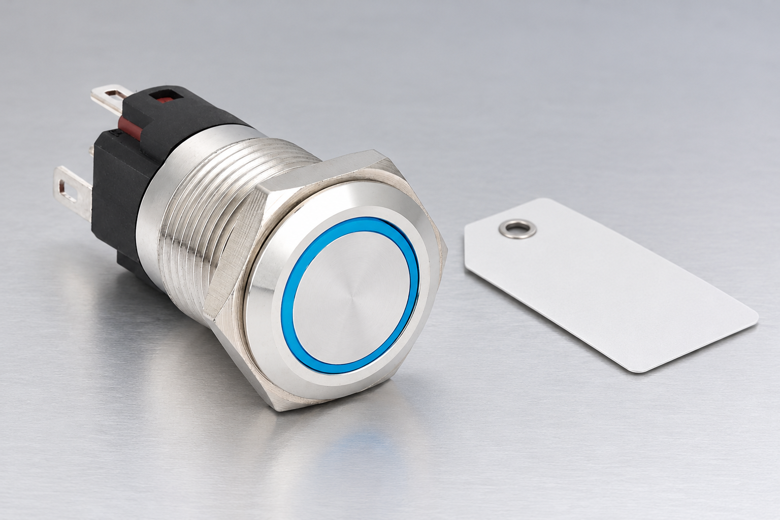
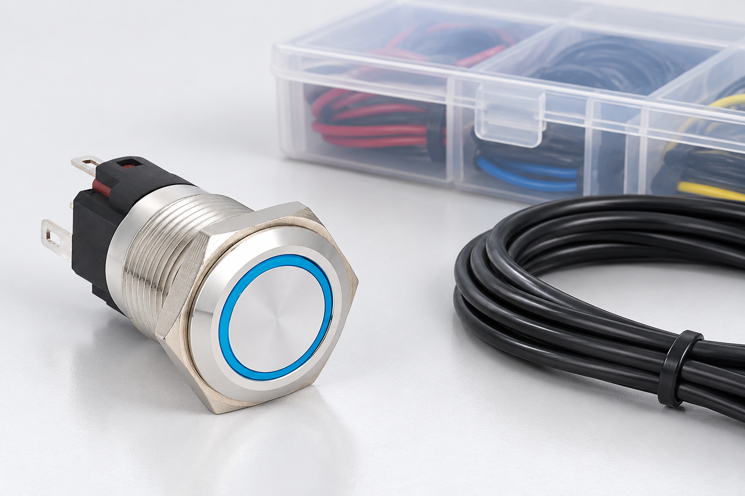
The ONPOW6116F-11E/S page provides a real ONPOW product reference. The photographs here preserve its visible operator and rear form. A compatible mating component is deliberately not invented or shown, and the images do not establish an order code for a harness or plug.
Obtain the current configured drawing and the applicable connection options from ONPOW. A series-level description of a quick connection does not identify every part needed for a particular order. Confirm the actual delivery scope before ordering a mating assembly or planning service spares.
Where a different rear option is proposed, review it as an interface change. The front operator can remain visually similar while the connection, service access or harness assignment changes. Preserve the approved configuration rather than relying on the panel appearance to identify the electrical interface.
Inspect a representative complete harness
Use the actual device, mating parts, conductors and production process for qualification. Record their identities and revisions. Inspect the completed assembly against the controlled drawing, including position assignment, permitted wire preparation and the required engagement features.
Use the equipment’s approved inspection and test plan to verify the relevant circuits. Test results should identify the boundary and conditions rather than simply stating that the harness “works.” Any energized functional work requires its own safe procedure and competent personnel; this article does not authorize live troubleshooting.
Retain a clear record of the accepted assembly and recurring rejection reasons. Receiving controls should confirm that later deliveries match it. The push button incoming inspection guide can help organize identification and discrepancy records without replacing the connector manufacturer’s acceptance requirements.
Control replacement and substitution decisions
A supplier change, contact change or revised wire construction can affect the interface even when the housing still appears to fit. Define which changes require re-evaluation and keep them linked to the equipment bill of materials. Do not let a purchasing substitution silently become a different wiring process.
List the intended service spare clearly: complete prewired assembly, mating half, loose contacts or another approved kit. Include the safe replacement and inspection instructions. This prevents a technician from receiving a component that cannot be assembled with the site’s available tools or authorized process.
Contact ONPOW with the exact switch code, harness requirements, drawing view and available rear space. A complete inquiry makes it possible to confirm the real interface and supply scope. It is more useful than asking whether a connector with the same number of positions will fit.
Často kladené otázky
Does the same connector position count mean compatibility?
No. Mechanical keying, contacts, dimensions, retention, wiring assignment and ratings can differ. Confirm the exact approved mating combination and configuration.
Can I rely on matching wire colors when replacing a harness?
Only when the controlled drawing defines those assignments for the exact assembly. Compare positions and circuit functions rather than assuming another supplier or revision uses the same colors.
Is a plug that clicks into place fully qualified?
No. Engagement is only one interface question. The circuit assignment, conductor preparation, relevant ratings, environment and service arrangement still need evidence.
Should a spare-parts order include the mating connector?
State the required supply scope explicitly. A switch, mating housing, contacts and complete harness can be separate items, so an image or family name alone is insufficient.
References and scope
HSE electrical maintenance safety supports the safe-working framework. NASA’s cable and harness workmanship standard page provides an example of controlled harness workmanship, not approval of an industrial connector combination. Use exact component documentation and the equipment’s approved requirements for the actual interface and acceptance limits.
Further learning
University background on planning inspection and quality evidence, using casting examples. Apply the acceptance-planning principle; this lecture does not identify a compatible mating connector.