

A 12V DC toggle switch must be chosen for the actual DC load, including steady current, startup or inrush current, inductive energy, switching frequency and wire protection. A switch advertised for 12 volts is not automatically suitable for every automotive, battery or industrial DC circuit, and an AC rating should not be treated as an equivalent DC rating. This guide explains a safe identification and verification process for engineers, panel builders, maintenance teams and buyers. It does not replace the current datasheet, machine risk assessment or locally applicable electrical requirements. The method keeps each decision traceable during purchasing, assembly, commissioning and later service.
Schnelle Entscheidung
Beginnen Sie mit der Funktion, nicht mit der Polzahl. Schreiben Sie die erforderlichen stabilen und tastenden Zustände auf, identifizieren Sie jeden Kontakt- und Lampenkreis und gleichen Sie dann die dokumentierte Nennleistung mit der tatsächlichen Last ab. Halten Sie die Stromversorgung während der Identifizierung getrennt. Testen Sie nach der Installation sowohl den elektrischen Zustand als auch die Maschinenreaktion. Wenn die Anwendung gefährliche Bewegungen steuert, verwenden Sie die erforderliche Sicherheitsarchitektur, anstatt einen Allzweckschalter als vollständige Sicherheitsfunktion zu behandeln.
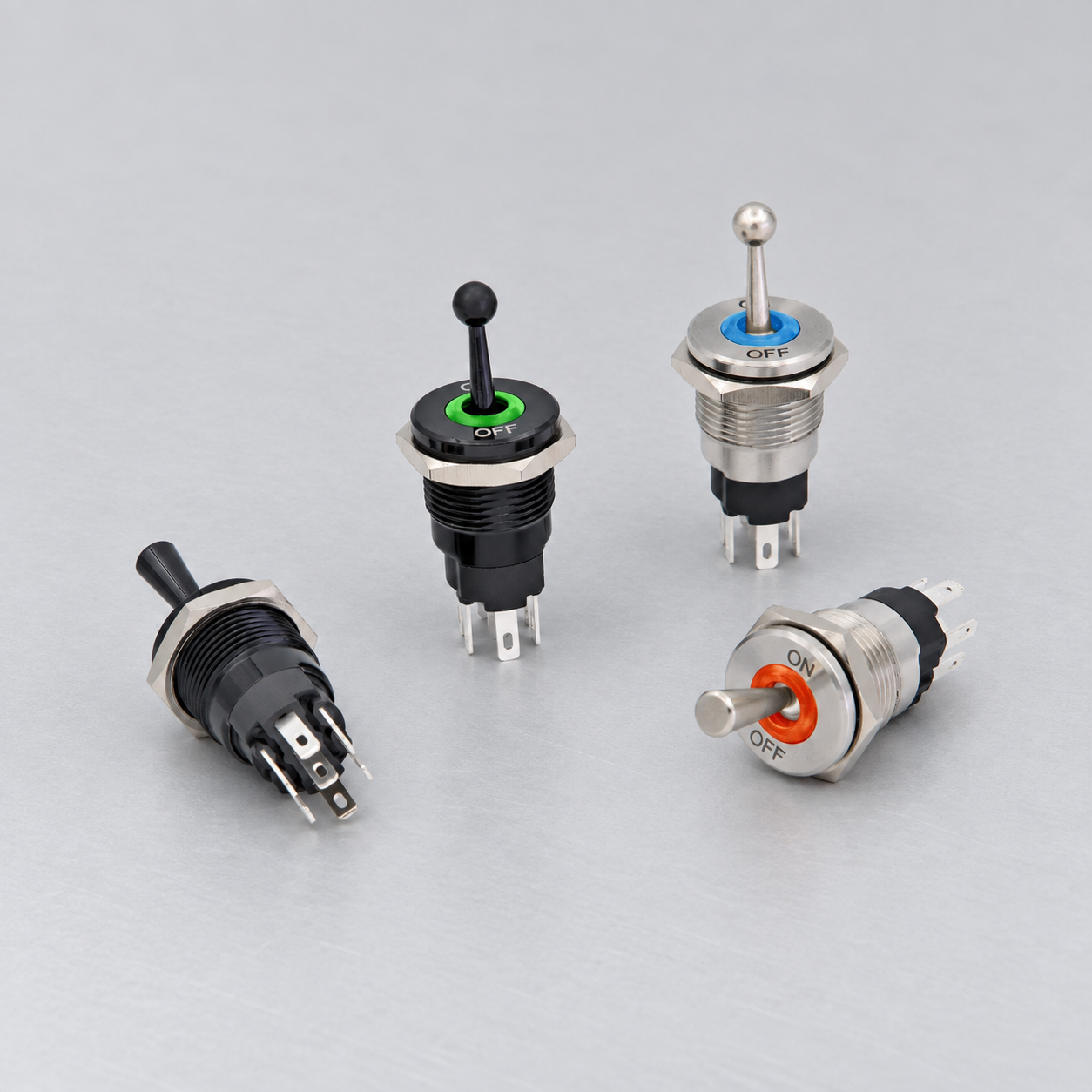
Auswahl- und Verdrahtungskriterien
| Entscheidung | Was zu überprüfen ist | technischer Grund |
|---|---|---|
| DC rating | Find an explicit rating at or above the actual DC voltage | AC and DC interruption produce different arc conditions. |
| Steady current | Calculate or measure normal load current | This establishes conductor and contact loading during operation. |
| Inrush current | Check lamps, motors, solenoids and capacitive inputs | Startup peaks can exceed the running current by a large application-dependent amount. |
| Inductive load | Provide manufacturer-approved suppression where appropriate | Stored magnetic energy raises contact voltage when the circuit opens. |
| Fuse or breaker | Protect wiring close to the energy source according to system design | A switch rating does not protect the conductor from a short circuit. |
| Voltage drop | Check terminals, wire length and contact resistance | Small losses matter more in low-voltage systems. |
| Illumination | Match LED module voltage and polarity | A 12V lamp circuit remains separate from the contact rating. |
| Umwelt | Include vibration, moisture, salt, heat and service access | Vehicles and battery systems can be harsher than a dry bench test. |
Diese Tabelle ist absichtlich qualitativ gehalten. Numerische Bewertungen, Drehmomente, Leitergrößen, Isolationsabstände, Lebensdauer- und Umweltgrenzwerte müssen den genehmigten Dokumenten für das genaue Gerät und der vollständigen Gerätetechnik entnommen werden. Ähnlich aussehende Schalter können unterschiedliche interne Anschlüsse verwenden.
Verstehen Sie die Kontaktlogik vor dem Verdrahten
Pol beschreibt, wie viele unabhängige gemeinsame Kontaktwege zusammenarbeiten. Schaltstellung (Throw) beschreibt, wie viele feste Kontakte jeder gemeinsame Kontakt anwählen kann. Diese Begriffe geben weder die Anzahl der Hebelstellungen an, noch ob eine Stellung rastend oder tastend ist, ob Kontakte beim Umschalten überlappen oder wie eine Kontrolllampe angeschlossen ist. Diese Details erfordern eine Kontakttabelle für jede einzelne Stellung.
Zeichnen Sie eine Matrix mit Klemmen oben und Aktorpositionen an der Seite. Markieren Sie nur Verbindungen, die durch die aktuelle Zeichnung oder durch isolierte Messungen unterstützt werden. Fügen Sie eine klare Blickrichtung wie “Ansicht der hinteren Klemmen bei nach oben gerichtetem Aktor” hinzu. Diese einfache Aufzeichnung verhindert, dass gespiegelte Diagramme, gedrehte Bauteile und Kabelsatz-Kammernummern bei der Montage oder späteren Wartung verwechselt werden.
DC rating
Was zu überprüfen ist: Find an explicit rating at or above the actual DC voltage. AC and DC interruption produce different arc conditions. The engineering record should name the exact order code, drawing revision, supply, load and operating state used for the decision. Check the component in its installed orientation because panel thickness, wire routing, adjacent hardware and actuator access can change the result.
Wie man es überprüft: Vergleichen Sie das aktuelle Hersteller-Kontaktdiagramm mit einer isolierten Durchgangsprüfung. Protokollieren Sie den gemessenen Zustand vor der Betätigung, in jeder rastenden Position und nach dem Loslassen aus jeder tastenden Position. Wenn Dokumentation und Messung nicht übereinstimmen, stoppen Sie und klären Sie die Abweichung, bevor Sie die Spannung einschalten. Leiten Sie niemals eine Klemmenfunktion von der Pin-Position, der Metallfarbe oder einem Diagramm für einen ähnlich aussehenden Schalter ab.
Steady current
Was zu überprüfen ist: Calculate or measure normal load current. This establishes conductor and contact loading during operation. The engineering record should name the exact order code, drawing revision, supply, load and operating state used for the decision. Check the component in its installed orientation because panel thickness, wire routing, adjacent hardware and actuator access can change the result.
Wie man es überprüft: Vergleichen Sie das aktuelle Hersteller-Kontaktdiagramm mit einer isolierten Durchgangsprüfung. Protokollieren Sie den gemessenen Zustand vor der Betätigung, in jeder rastenden Position und nach dem Loslassen aus jeder tastenden Position. Wenn Dokumentation und Messung nicht übereinstimmen, stoppen Sie und klären Sie die Abweichung, bevor Sie die Spannung einschalten. Leiten Sie niemals eine Klemmenfunktion von der Pin-Position, der Metallfarbe oder einem Diagramm für einen ähnlich aussehenden Schalter ab.
Inrush current
Was zu überprüfen ist: Check lamps, motors, solenoids and capacitive inputs. Startup peaks can exceed the running current by a large application-dependent amount. The engineering record should name the exact order code, drawing revision, supply, load and operating state used for the decision. Check the component in its installed orientation because panel thickness, wire routing, adjacent hardware and actuator access can change the result.
Wie man es überprüft: Vergleichen Sie das aktuelle Hersteller-Kontaktdiagramm mit einer isolierten Durchgangsprüfung. Protokollieren Sie den gemessenen Zustand vor der Betätigung, in jeder rastenden Position und nach dem Loslassen aus jeder tastenden Position. Wenn Dokumentation und Messung nicht übereinstimmen, stoppen Sie und klären Sie die Abweichung, bevor Sie die Spannung einschalten. Leiten Sie niemals eine Klemmenfunktion von der Pin-Position, der Metallfarbe oder einem Diagramm für einen ähnlich aussehenden Schalter ab.
Inductive load
Was zu überprüfen ist: Provide manufacturer-approved suppression where appropriate. Stored magnetic energy raises contact voltage when the circuit opens. The engineering record should name the exact order code, drawing revision, supply, load and operating state used for the decision. Check the component in its installed orientation because panel thickness, wire routing, adjacent hardware and actuator access can change the result.
Wie man es überprüft: Vergleichen Sie das aktuelle Hersteller-Kontaktdiagramm mit einer isolierten Durchgangsprüfung. Protokollieren Sie den gemessenen Zustand vor der Betätigung, in jeder rastenden Position und nach dem Loslassen aus jeder tastenden Position. Wenn Dokumentation und Messung nicht übereinstimmen, stoppen Sie und klären Sie die Abweichung, bevor Sie die Spannung einschalten. Leiten Sie niemals eine Klemmenfunktion von der Pin-Position, der Metallfarbe oder einem Diagramm für einen ähnlich aussehenden Schalter ab.
Fuse or breaker
Was zu überprüfen ist: Protect wiring close to the energy source according to system design. A switch rating does not protect the conductor from a short circuit. The engineering record should name the exact order code, drawing revision, supply, load and operating state used for the decision. Check the component in its installed orientation because panel thickness, wire routing, adjacent hardware and actuator access can change the result.
Wie man es überprüft: Vergleichen Sie das aktuelle Hersteller-Kontaktdiagramm mit einer isolierten Durchgangsprüfung. Protokollieren Sie den gemessenen Zustand vor der Betätigung, in jeder rastenden Position und nach dem Loslassen aus jeder tastenden Position. Wenn Dokumentation und Messung nicht übereinstimmen, stoppen Sie und klären Sie die Abweichung, bevor Sie die Spannung einschalten. Leiten Sie niemals eine Klemmenfunktion von der Pin-Position, der Metallfarbe oder einem Diagramm für einen ähnlich aussehenden Schalter ab.
Voltage drop
Was zu überprüfen ist: Check terminals, wire length and contact resistance. Small losses matter more in low-voltage systems. The engineering record should name the exact order code, drawing revision, supply, load and operating state used for the decision. Check the component in its installed orientation because panel thickness, wire routing, adjacent hardware and actuator access can change the result.
Wie man es überprüft: Vergleichen Sie das aktuelle Hersteller-Kontaktdiagramm mit einer isolierten Durchgangsprüfung. Protokollieren Sie den gemessenen Zustand vor der Betätigung, in jeder rastenden Position und nach dem Loslassen aus jeder tastenden Position. Wenn Dokumentation und Messung nicht übereinstimmen, stoppen Sie und klären Sie die Abweichung, bevor Sie die Spannung einschalten. Leiten Sie niemals eine Klemmenfunktion von der Pin-Position, der Metallfarbe oder einem Diagramm für einen ähnlich aussehenden Schalter ab.
Illumination
Was zu überprüfen ist: Match LED module voltage and polarity. A 12V lamp circuit remains separate from the contact rating. The engineering record should name the exact order code, drawing revision, supply, load and operating state used for the decision. Check the component in its installed orientation because panel thickness, wire routing, adjacent hardware and actuator access can change the result.
Wie man es überprüft: Vergleichen Sie das aktuelle Hersteller-Kontaktdiagramm mit einer isolierten Durchgangsprüfung. Protokollieren Sie den gemessenen Zustand vor der Betätigung, in jeder rastenden Position und nach dem Loslassen aus jeder tastenden Position. Wenn Dokumentation und Messung nicht übereinstimmen, stoppen Sie und klären Sie die Abweichung, bevor Sie die Spannung einschalten. Leiten Sie niemals eine Klemmenfunktion von der Pin-Position, der Metallfarbe oder einem Diagramm für einen ähnlich aussehenden Schalter ab.
Umwelt
Was zu überprüfen ist: Include vibration, moisture, salt, heat and service access. Vehicles and battery systems can be harsher than a dry bench test. The engineering record should name the exact order code, drawing revision, supply, load and operating state used for the decision. Check the component in its installed orientation because panel thickness, wire routing, adjacent hardware and actuator access can change the result.
Wie man es überprüft: Vergleichen Sie das aktuelle Hersteller-Kontaktdiagramm mit einer isolierten Durchgangsprüfung. Protokollieren Sie den gemessenen Zustand vor der Betätigung, in jeder rastenden Position und nach dem Loslassen aus jeder tastenden Position. Wenn Dokumentation und Messung nicht übereinstimmen, stoppen Sie und klären Sie die Abweichung, bevor Sie die Spannung einschalten. Leiten Sie niemals eine Klemmenfunktion von der Pin-Position, der Metallfarbe oder einem Diagramm für einen ähnlich aussehenden Schalter ab.
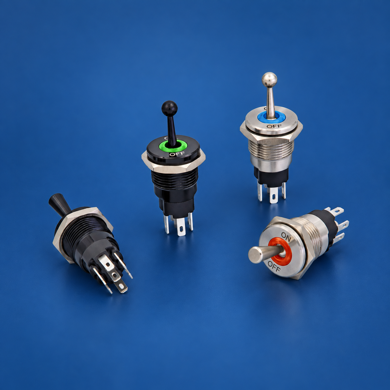
Sichere Identifizierung und Inbetriebnahmereihenfolge
- Definiere die Funktion. Geben Sie an, was jede Aktuatorposition ansteuern soll, was beim Loslassen passiert und wie der Normalzustand nach einem Stromausfall sein muss.
- Confirm identity. Photograph the marking and record the complete order code. Retrieve the matching current drawing rather than a family brochure.
- Isolate energy. Follow the site procedure for disconnecting and controlling hazardous energy. Prove the circuit is de-energized with appropriate equipment before touching conductors.
- Separate the component. Disconnect enough conductors to prevent parallel circuit paths from corrupting continuity measurements. Label every removed conductor.
- Map contacts. Test all terminal pairs in all positions. Repeat the sequence to detect intermittent behavior and note any spring-return action.
- Identify lamps separately. Use the published lamp diagram and voltage. Do not apply an unknown test voltage to an LED or electronic module.
- Review the load. Check normal current, inrush, AC or DC, inductive energy, switching frequency, protection and the consequence of a contact failing open or closed.
- Install mechanically. Confirm cutout, panel thickness, anti-rotation, fasteners, sealing, rear clearance, conductor support and accessible labels.
- Perform an unpowered check. Verify point-to-point wiring and insulation before energizing. Make sure unused terminals cannot contact adjacent conductive parts.
- Commission under control. Energize according to the equipment procedure, test each command and indication, then test loss and restoration of power and the credible faults identified by the risk assessment.
Load and protection boundaries
Contact ratings are conditional. A resistive laboratory load does not represent every motor, solenoid, lamp, heater, electronic power supply or capacitive input. DC interruption can sustain an arc differently from AC. Inductive loads release stored energy when opened, and cold lamps or capacitors may draw high inrush. Obtain the load data and apply only a rating that explicitly covers the intended conditions.
The switch is also not the branch-circuit protective device. Conductor size, fuse or breaker selection, short-circuit capability, grounding, insulation and enclosure protection belong to the wider equipment design. Where the operator should carry only a low-energy command, use a properly selected relay, contactor or controller input and verify the interface. Suppression components must suit the supply, load and failure behavior.
Common mistakes
- DC rating: AC and DC interruption produce different arc conditions. Prevent this by completing the related verification step—find an explicit rating at or above the actual dc voltage—and retaining the evidence with the machine documentation.
- Steady current: This establishes conductor and contact loading during operation. Prevent this by completing the related verification step—calculate or measure normal load current—and retaining the evidence with the machine documentation.
- Inrush current: Startup peaks can exceed the running current by a large application-dependent amount. Prevent this by completing the related verification step—check lamps, motors, solenoids and capacitive inputs—and retaining the evidence with the machine documentation.
- Inductive load: Stored magnetic energy raises contact voltage when the circuit opens. Prevent this by completing the related verification step—provide manufacturer-approved suppression where appropriate—and retaining the evidence with the machine documentation.
- Fuse or breaker: A switch rating does not protect the conductor from a short circuit. Prevent this by completing the related verification step—protect wiring close to the energy source according to system design—and retaining the evidence with the machine documentation.
- Voltage drop: Small losses matter more in low-voltage systems. Prevent this by completing the related verification step—check terminals, wire length and contact resistance—and retaining the evidence with the machine documentation.
What to include in an RFQ
Provide the contact form, actuator positions, maintained or momentary action, center state, lamp function and voltage, supply, load category, normal and inrush current, switching frequency, panel cutout, panel thickness, rear-space limit, terminal preference, environment, ingress requirement, temperature range, vibration, required documentation, quantity and target market. Ask the supplier to return the exact contact table and dimensional drawing for the proposed order code.
Use the ONPOW industrial control product range to identify candidate families. Final selection must be based on the exact model documentation and validation in the completed assembly. For an unusual harness or control sequence, provide a terminal-view sketch and ask the supplier to mark any assumptions before samples are ordered.
Related ONPOW guides
- Toggle switch position basics
- Toggle switch and push button comparison
- Normally open and normally closed contacts
Authoritative references
- IEC 60947-5-1 control-circuit devices
- IEC 60204-1 electrical equipment of machines
- OSHA electrical safety requirements
Educational video
Electrical Basics – Switches and Contacts by HVAC School provides general background. The exact switch and equipment still require their own documentation and validation.
Frequently asked questions
Können die Anschlusspositionen auf einem Foto dieses Kippschalters identifiziert werden?
Nein. Ein Foto kann zwar die Verpackung und die Anzahl der Anschlüsse zeigen, aber es kann nicht zuverlässig die interne Kontaktanordnung, die Blickrichtung, den Lampenkreis oder die Nennleistung feststellen. Verwenden Sie die exakte Modellzeichnung und einen isolierten Test.
Gilt der aufgedruckte Amperewert für jede Last?
Nein. Der zulässige Wert hängt von der Spannung, AC oder DC, der Lastkategorie, dem Einschaltstrom, der Schalthäufigkeit, der Temperatur und den Hersteller-Testbedingungen ab. Wählen Sie aus den für die jeweilige Anwendung angegebenen Nennwerten aus.
Kann ein Durchgangsprüfer verwendet werden, um Kontakte zu identifizieren?
Ja, wenn alle Quellen isoliert und gespeicherte Energie entladen ist. Prüfen Sie jede Position, berücksichtigen Sie, dass Lampenstromkreise Widerstandswerte erzeugen können, und vergleichen Sie die Matrix mit der Dokumentation des Herstellers.
Soll der Schalter einen Motor- oder Magnetspulenstrom direkt schalten?
Nur wenn die genaue Last und Einschaltdauer innerhalb der dokumentierten Nennwerte liegen. Bei höherem Einschaltstrom, häufigem Betrieb oder sicherheitskritischen Maschinen ist ein entsprechend ausgewähltes Relais oder Schütz oft die bessere Schnittstelle.
Welche Informationen gehören in das endgültige Verdrahtungsprotokoll?
Erfassen Sie den Bestellcode, die Ansichtsrichtung der Klemmen, die Kontaktmatrix, die Leiterkennzeichnungen, die Schutzeinrichtung, die Einspeisung, die Last, die Beschriftungen, die Prüfergebnisse, die Dokumentenrevisionen und das Genehmigungsdatum.
Final verification rule
Approve the installation only when the exact device identity, contact matrix, lamp behavior, mechanical fit, environmental boundary, load rating, protective measures, labels and test results all agree. Resolve every discrepancy before energizing production equipment. Keep the final record with the machine so a later replacement is checked against evidence rather than appearance.



