

The choice between an electromechanical relay and a solid-state relay depends on the load, switching duty, off-state behavior, heat management, and required failure response. An electromechanical relay uses moving contacts operated by a coil. A solid-state relay switches through semiconductor devices controlled by an input circuit. Neither technology is automatically better: a mechanical contact may suit infrequent switching and a particular contact arrangement, while a suitable solid-state design may suit frequent operation. Start with the circuit and operating conditions, then compare exact datasheets. Do not replace one with the other simply because their advertised current ratings look similar.
Compare the switching mechanisms first
An electromechanical relay moves an armature and contact assembly when its coil is energized. An ordinary non-latching type returns to its resting state when coil power is removed. The moving contacts can switch appropriate circuits, but they also introduce operating time, bounce, mechanical wear, and electrical wear under load. The load and switching frequency influence the useful electrical life.
A solid-state relay uses an electronic input and a semiconductor output stage. The output may use devices intended for AC or DC, and those choices affect when and how the load can be switched. An SSR intended for one supply type should not be assumed suitable for the other. Its internal isolation, leakage, voltage drop, transient protection, and thermal requirements must be checked as product-specific features.
The original Lessons in Electric Circuits relay chapter explains both relay mechanisms. It is useful background, not a universal wiring diagram. The real comparison must use the selected device’s published limits and the installation conditions under which those limits apply.
Define the load before comparing ratings
Write down the supply waveform, voltage range, running current, startup behavior, operating cycle, and switching frequency. A resistive heater, a motor, a solenoid, a transformer, and an electronic power supply can impose very different stresses. The number printed most prominently on a relay listing is not enough to decide whether it can switch the intended load.
An electromechanical relay can experience arcing and contact erosion when opening an unsuitable or poorly protected load. An SSR can be damaged by excessive current, voltage transients, or heat. Protection requirements belong to the complete circuit, including upstream protection and the expected fault conditions. Neither technology eliminates the need to review the actual application.
For the mechanical side, use the relay contact rating guide to separate load categories and duty. When comparing an SSR, look for explicit evidence for the same load and supply conditions. A seller’s headline rating without the associated thermal conditions or load restrictions is an unresolved question, not a confirmed match.
Use a comparison table to organize evidence
This table identifies differences to investigate. It does not assign universal performance values or promise that every product in a technology family behaves identically. The Saylor-hosted electrical circuits textbook provides the educational background; exact values come from the selected datasheets.
| Punto de decisión | Electromechanical relay review | Solid-state relay review |
|---|---|---|
| Load compatibility | Check contact ratings for actual AC/DC duty, inrush and switching frequency | Check output device type, AC/DC compatibility, surge limits and protection |
| Frequent switching | Evaluate electrical and mechanical life for the intended cycle | Evaluate thermal behavior, duty and input/output timing |
| Off condition | Confirm the contact state and insulation; consider welded-contact faults | Check leakage, residual voltage, minimum load and short-circuit faults |
| Heat in the enclosure | Account for coil heating and contact/terminal conditions | Account for conduction losses and the required mounting or heat sink |
| Controller interface | Match coil demand and approved suppression to the driver | Match input voltage/current, thresholds and polarity to the driver |
| Mantenimiento | Confirm exact replacement code, socket and retention arrangement | Confirm replacement specification, mounting, thermal interface and protection |
| Machine fault response | Analyze stuck or welded contacts and loss of coil supply | Analyze semiconductor failure and loss or corruption of the input signal |
Use the table as a request for evidence. If one column contains unknowns, do not fill them with assumptions just to finish a selection. A slower but documented decision is more useful than an apparently simple replacement that changes the machine’s response.
Off-state leakage can affect a small load
An open mechanical contact and an SSR’s off state are not interchangeable circuit conditions. Semiconductor outputs can pass leakage current when commanded off. Depending on the exact load, that may create a measurable voltage, a faint indicator glow, or an unexpected input response. The effect depends on the SSR, load impedance, and associated circuitry.
Do not infer that a circuit is safe to touch because its indicator is dark or its control input is off. Also do not add a resistor or other component from a generic example without checking the electrical design, power dissipation, and equipment requirements. A residual voltage should be investigated by qualified personnel using a suitable measurement method.
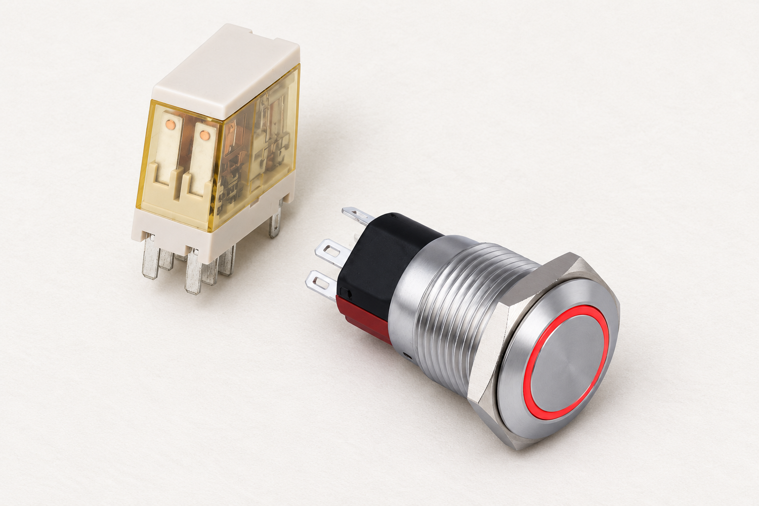
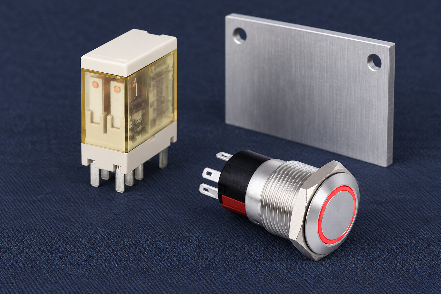
For a panel using illuminated controls, identify lamp supply and button contact functions separately. An ONPOW6116 button can be considered as an operator interface after its exact configuration is verified, but the ring color or face shape does not establish whether it is compatible with either relay input. The illustrations show a real button and an electromechanical relay, not an ONPOW SSR product claim.
Heat management can decide the comparison
Mechanical relays generate heat in their coils and current-carrying paths. Semiconductor relays can generate appreciable heat while conducting, and an advertised current may depend on a particular heat sink, ambient temperature, airflow, or mounting condition. A bare device on a bench is not equivalent to the installed component inside a crowded cabinet.
Obtain the selected SSR’s thermal instructions, derating information, and mounting requirements. Confirm how its heat will leave the enclosure under the worst intended operating condition. For either technology, review terminal connections and surrounding heat sources. Avoid treating an enclosure’s external temperature as a direct measurement of every internal junction or contact condition.
The useful procurement question is not simply whether a device needs a heat sink. Ask what installation supports the intended current and duty, what evidence verifies that installation, and what happens when ventilation changes. If the required thermal design cannot be accommodated, revisit the switching arrangement rather than ignoring the condition attached to the rating.
Switching speed is useful only when the process needs it
An SSR may support frequent or fast switching without moving contacts, but its response still depends on the output design. Some AC SSRs use zero-crossing operation; others respond differently. Zero-crossing behavior is not the same thing as instant response to every command, and it should not be assumed appropriate for every load or control method.
A mechanical relay’s timing includes the coil response, armature movement, and contact settling. It may be perfectly adequate for an infrequent operator command while being unsuitable for a rapid repetitive control cycle. Decide the required process behavior first, then compare documented timing under the intended conditions.
Avoid choosing a faster device simply because speed sounds like an improvement. A technology change can alter power-up behavior, the interpretation of an off command, noise, fault detection, and maintenance procedures. Those changes deserve review even when the replacement fits in the same cabinet space.
Check the controller interface and suppression
For an electromechanical relay, the driver must support the selected coil and its approved suppression. A DC coil can generate a transient when its current is interrupted. A protection arrangement can affect release timing, so use the coil suppression guide alongside the product instructions.
For an SSR, review the input circuit’s voltage/current requirements, thresholds, polarity, and any specified leakage restrictions on the controller output. An output that successfully drives a mechanical coil may not behave identically with an electronic input, and the reverse is also possible. Check startup, shutdown, and abnormal supply conditions rather than testing only a stable on command.
If the operator button goes into a PLC input, keep that interface separate from the relay output design. The controller logic can command either technology, but changing the output device does not validate the button circuit, control program, or machine function. The relay selection guide gives a broader checklist for those boundaries.
Plan for failures and safe maintenance
Both technologies can fail in ways that leave a load energized or prevent it from operating. Do not claim that mechanical relays always fail open or SSRs always fail short. Analyze the selected component, circuit, diagnostics, and required machine response. A single general-purpose switching device should not be presented as a complete safety function.
Before servicing an installation, use its approved energy-control procedure. The official 2025 CFR edition of section 1910.333 addresses electrical work practices in the U.S. workplace context. An off command, a removed input signal, or a relay replacement is not by itself proof that all hazardous energy has been isolated.
For further learning, Lars Kristjansen’s contact demonstration explains the mechanical relay side of this comparison. It does not demonstrate an SSR or recommend a model-specific substitution.

Preguntas frecuentes
Is a solid-state relay always better than a mechanical relay?
No. The right choice depends on the actual load, switching duty, leakage tolerance, thermal design, controller interface, and required failure response. Compare the complete application with exact datasheets instead of ranking technologies in isolation.
Can equal current ratings justify a direct replacement?
No. A rating may depend on load type, waveform, temperature, mounting, and duty. A replacement also needs compatible input behavior, protection, off-state performance, physical installation, and verified machine operation.
Why might an indicator glow with an SSR off?
Off-state leakage and the load’s impedance can produce a visible or measurable effect. Confirm the exact circuit and device specifications. Do not improvise a correction or use the indicator state as an isolation check.
Do all SSRs need the same heat sink?
No. Thermal requirements depend on the selected device, current, duty, ambient conditions, and mounting. Follow its thermal instructions and derating evidence; a generic heat sink photograph does not establish adequacy.
Which technology should control an emergency stop function?
The technology name alone cannot answer that question. The safety function requires an appropriate architecture, component evidence, diagnostics, and validation. Neither an ordinary relay nor a general-purpose SSR is automatically a complete emergency-stop solution.



