

Electromechanical relay selection requires separate checks for the coil circuit, contact circuit, mechanical format, environment, and failure behavior. Start with the control voltage and available coil drive, then define the real load—including inrush, inductive behavior, switching frequency, and required isolation. Choose the contact form, socket or mounting method, protection components, and replacement strategy only after those boundaries are clear. A relay’s headline current is not a universal permission to switch any load at that current.
Respuesta corta: La selección es una decisión del sistema. Confirme conjuntamente la interfaz mecánica, la interfaz eléctrica, el entorno, la respuesta humana, el plan de mantenimiento y las normas aplicables. Los ejemplos siguientes son orientaciones para la toma de decisiones, no valoraciones universales de productos.
Cómo funciona el dispositivo o sistema
When the coil is energized, its magnetic field moves an armature and changes one or more contacts. This allows a relatively low-power control signal to switch another circuit and can provide galvanic separation when the device is used within its ratings. De-energizing the coil returns a monostable relay to its normal position; latching versions behave differently. The coil is an inductive load and releases stored energy when switched off, so the drive circuit may need suppression. Suppression choice affects voltage stress and release time and must match AC or DC operation and the control design.

Criterios de selección de un vistazo
| Área de decisión | Qué verificar | Por qué importa |
|---|---|---|
| Coil | Confirm nominal voltage, allowable range, AC/DC type, power, pickup, dropout, and drive capability | A nominal match alone does not prove reliable operation during supply tolerance or temperature change. |
| Contact form | Choose the required poles and NO, NC, or changeover arrangement | Use the de-energized state and failure strategy to define the circuit, not a familiar pin pattern. |
| Load category | Identify resistive, inductive, capacitive, lamp, motor, or electronic load and its inrush | Contact life and permissible current can change greatly with load behavior. |
| Switching duty | Define operations per hour, expected life, bounce sensitivity, and release timing | Frequent operation may favor a different relay technology or derating strategy. |
| Isolation | Check coil-to-contact and contact-to-contact insulation requirements | System working voltage, pollution, wiring, PCB or socket design all contribute to the final insulation result. |
| Suppression | Coordinate coil suppression and load suppression with the control system | A diode, RC network, or varistor changes voltage stress and sometimes release speed; one solution does not fit every circuit. |
| Mechanical format | Verify plug-in socket, PCB, DIN adapter, retaining clip, dimensions, and terminal numbering | Serviceability and wiring errors depend on the complete relay-and-socket combination. |
| Medio ambiente | Review temperature, vibration, shock, dust, condensation, altitude, and corrosive atmosphere | Environmental stress can affect coil temperature, contacts, insulation, and mechanical operation. |
La tabla es deliberadamente cualitativa. Los límites numéricos deben provenir de la hoja de datos actual para el modelo exacto y de las condiciones de diseño de la máquina. No transfiera un valor de un producto de apariencia similar, otro voltaje, otra categoría de carga o la página de un competidor.
Cómo hacer la selección
Coil
Confirm nominal voltage, allowable range, AC/DC type, power, pickup, dropout, and drive capability This matters because a nominal match alone does not prove reliable operation during supply tolerance or temperature change. Record the chosen value, the source document, and the condition under which it applies. If the requirement cannot be verified from the current product documentation, keep it open for supplier confirmation rather than filling the gap with an assumption.
Contact form
Choose the required poles and NO, NC, or changeover arrangement This matters because use the de-energized state and failure strategy to define the circuit, not a familiar pin pattern. Record the chosen value, the source document, and the condition under which it applies. If the requirement cannot be verified from the current product documentation, keep it open for supplier confirmation rather than filling the gap with an assumption.
Load category
Identify resistive, inductive, capacitive, lamp, motor, or electronic load and its inrush This matters because contact life and permissible current can change greatly with load behavior. Record the chosen value, the source document, and the condition under which it applies. If the requirement cannot be verified from the current product documentation, keep it open for supplier confirmation rather than filling the gap with an assumption.
Switching duty
Define operations per hour, expected life, bounce sensitivity, and release timing This matters because frequent operation may favor a different relay technology or derating strategy. Record the chosen value, the source document, and the condition under which it applies. If the requirement cannot be verified from the current product documentation, keep it open for supplier confirmation rather than filling the gap with an assumption.
Isolation
Check coil-to-contact and contact-to-contact insulation requirements This matters because system working voltage, pollution, wiring, PCB or socket design all contribute to the final insulation result. Record the chosen value, the source document, and the condition under which it applies. If the requirement cannot be verified from the current product documentation, keep it open for supplier confirmation rather than filling the gap with an assumption.
Suppression
Coordinate coil suppression and load suppression with the control system This matters because a diode, RC network, or varistor changes voltage stress and sometimes release speed; one solution does not fit every circuit. Record the chosen value, the source document, and the condition under which it applies. If the requirement cannot be verified from the current product documentation, keep it open for supplier confirmation rather than filling the gap with an assumption.
Mechanical format
Verify plug-in socket, PCB, DIN adapter, retaining clip, dimensions, and terminal numbering This matters because serviceability and wiring errors depend on the complete relay-and-socket combination. Record the chosen value, the source document, and the condition under which it applies. If the requirement cannot be verified from the current product documentation, keep it open for supplier confirmation rather than filling the gap with an assumption.
Medio ambiente
Review temperature, vibration, shock, dust, condensation, altitude, and corrosive atmosphere This matters because environmental stress can affect coil temperature, contacts, insulation, and mechanical operation. Record the chosen value, the source document, and the condition under which it applies. If the requirement cannot be verified from the current product documentation, keep it open for supplier confirmation rather than filling the gap with an assumption.

Revisión de la solicitud
Utilice los siguientes escenarios como indicaciones para una revisión de ingeniería. No establecen idoneidad por sí mismos:
- Interface a plc output with a field circuit after coil-drive limits are confirmed. During commissioning, verify the command, expected response, abnormal response, and reset behavior in the assembled machine.
- Switch several isolated contact signals from one control command. During commissioning, verify the command, expected response, abnormal response, and reset behavior in the assembled machine.
- Provide a replaceable plug-in interface for maintenance-friendly control panels. During commissioning, verify the command, expected response, abnormal response, and reset behavior in the assembled machine.
- Use interposing contacts to separate control-system and machine-circuit responsibilities. During commissioning, verify the command, expected response, abnormal response, and reset behavior in the assembled machine.
- Select a different technology when switching frequency, silent operation, or lifetime requirements exceed electromechanical capability. During commissioning, verify the command, expected response, abnormal response, and reset behavior in the assembled machine.
Para cada caso, incluya los extremos de tolerancia, puesta en marcha, parada, pérdida de energía, restauración de energía, modo de mantenimiento, uso previsible mal intencionado o incorrecto, y sustitución de componentes. Cuando el comando afecte a la seguridad del personal, la función de seguridad debe diseñarse y validarse de forma independiente al control de procesos ordinario.
Puesta en marcha y verificación
- Congelar el requisito. Escribe el estado deseado, la acción del operador, la carga, el suministro, el entorno y el tiempo de respuesta en lenguaje sencillo.
- Verifica el modelo exacto. Relacione el código de pedido con su dibujo actual, tabla de clasificaciones, diagrama de terminales e instrucciones.
- Inspeccione la instalación. Confirmar recorte, elementos de fijación, alineación, entrada de cables, holgura trasera, alivio de tensión y protección de partes bajo tensión.
- Prueba de funcionamiento normal. Ejercite el dispositivo en todo el rango de movimiento, usuarios, cargas y condiciones ambientales esperados.
- Probar condiciones anormales. Incluya un cable desconectado, un mecanismo atascado, la pérdida de suministro, la contaminación y otros fallos identificados por la evaluación de riesgos.
- Registrar resultados. Mantener modelo, revisión, método de prueba, fecha, criterios de aceptación, observaciones medidas y aprobador.
- Planifique revisiones periódicas. Base los intervalos de inspección y sustitución en el uso, el entorno, la criticidad y el desgaste observado, y no en un programa universal inventado.
Errores comunes de selección
- Choosing from contact current alone while ignoring load category and inrush. Evite esto asignando un responsable, registrando el plano o la hoja de datos correspondiente y probando la instalación real en lugar de confiar en el nombre de un producto o en la imagen de un catálogo.
- Driving a dc coil without considering turn-off transient protection. Evite esto asignando un responsable, registrando el plano o la hoja de datos correspondiente y probando la instalación real en lugar de confiar en el nombre de un producto o en la imagen de un catálogo.
- Adding a suppression diode without checking its effect on release time. Evite esto asignando un responsable, registrando el plano o la hoja de datos correspondiente y probando la instalación real en lugar de confiar en el nombre de un producto o en la imagen de un catálogo.
- Assuming identical-looking plug-in relays share the same pinout. Evite esto asignando un responsable, registrando el plano o la hoja de datos correspondiente y probando la instalación real en lugar de confiar en el nombre de un producto o en la imagen de un catálogo.
- Mixing safety and ordinary control functions without the required architecture. Evite esto asignando un responsable, registrando el plano o la hoja de datos correspondiente y probando la instalación real en lugar de confiar en el nombre de un producto o en la imagen de un catálogo.
- Placing the relay in a hot enclosure without checking coil and contact derating. Evite esto asignando un responsable, registrando el plano o la hoja de datos correspondiente y probando la instalación real en lugar de confiar en el nombre de un producto o en la imagen de un catálogo.
Qué incluir en una consulta a proveedores
Una consulta útil debe indicar la aplicación, el mercado objetivo, las normas aplicables, los detalles de alimentación y carga, la interfaz de control, el plano mecánico, las dimensiones de montaje o del panel, el método de cableado, el entorno, la frecuencia de operación prevista, la cantidad y la documentación requerida. Añada fotografías o un boceto de movimiento cuando el enfoque del actuador o el uso por parte del operador sean difíciles de describir. Pida al proveedor que identifique las suposiciones y excepciones. Para un diseño nuevo o modificado, obtenga muestras y complete la validación antes de realizar pedidos en volumen.
ONPOW ofrece ONPOW industrial relay products dentro de su contexto más amplio gama de productos de control industrial. Utilice las páginas de productos para identificar las familias candidatas, luego confirme el modelo exacto con la información técnica actual y las condiciones de su proyecto.
Lectura relacionada de ONPOW
Referencias autorizadas
Video educativo
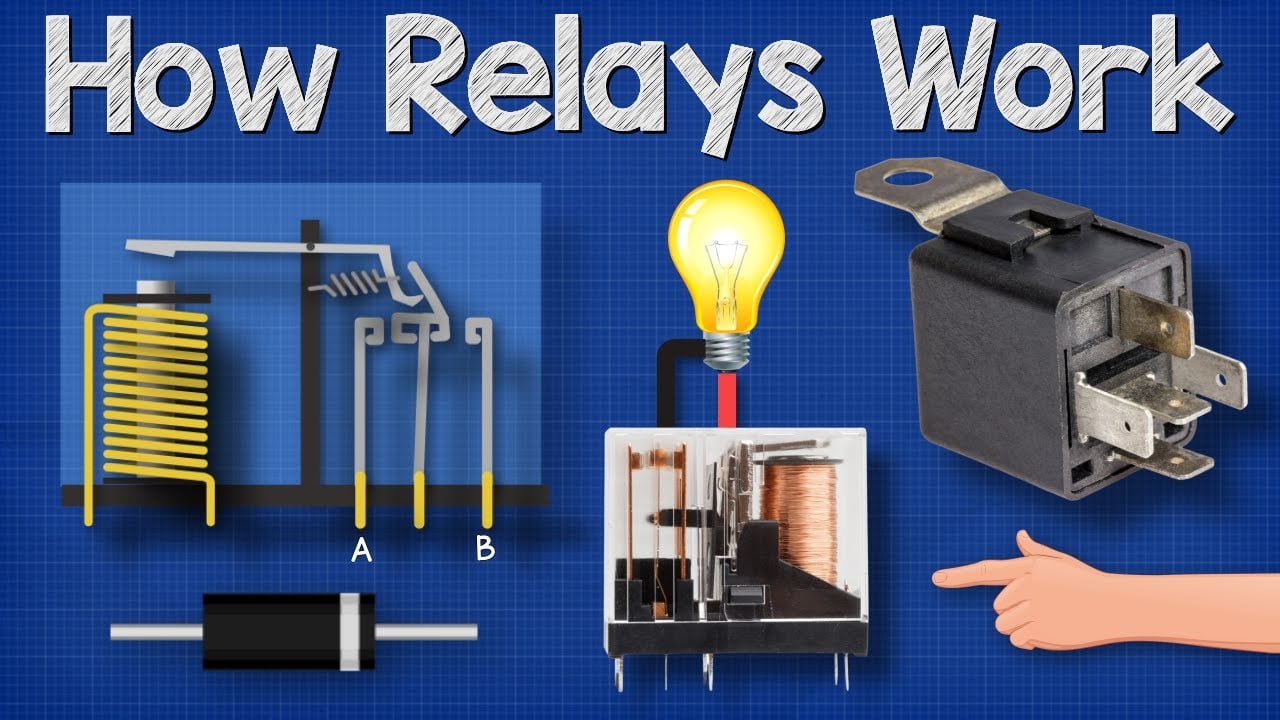
Further learning: How Relays Work — Basic Working Principle by The Engineering Mindset. The video explains the underlying concept; the project must still follow its own risk assessment and manufacturer documentation.
Preguntas frecuentes
¿Qué es un relé electromecánico?
Es un interruptor de funcionamiento eléctrico que utiliza una bobina, un mecanismo magnético y contactos físicos para cambiar uno o más circuitos.
¿Qué significa SPDT o DPDT?
SPDT describe un polo con dos tiros; DPDT describe dos polos de este tipo operados juntos. Confirme siempre el diagrama de terminales del fabricante.
¿Por qué importa el tipo de carga?
Los motores, solenoides, lámparas, condensadores y fuentes de alimentación electrónicas pueden tener una corriente de irrupción o energía almacenada muy diferente a la de una carga resistiva estable.
¿Cuándo es útil un socket?
A socket can simplify wiring and replacement, but adds dimensions, terminal ratings, retention, and installation requirements that must be checked as a system.
Should every relay coil have a diode?
No. A diode is common for some DC coils, but polarity and slower release may be important. AC coils and other control objectives require different solutions.
Regla de selección final
Elija el componente solo cuando sus límites mecánicos, eléctricos, ambientales, de usabilidad y de mantenimiento documentados encajen en el sistema ensamblado. Si un límite permanece desconocido, trátelo como una cuestión de ingeniería abierta. Un breve retraso de validación es menos costoso que diseñar en torno a una suposición que aparece solo después de la instalación.



