

Electromechanical relay selection requires separate checks for the coil circuit, contact circuit, mechanical format, environment, and failure behavior. Start with the control voltage and available coil drive, then define the real load—including inrush, inductive behavior, switching frequency, and required isolation. Choose the contact form, socket or mounting method, protection components, and replacement strategy only after those boundaries are clear. A relay’s headline current is not a universal permission to switch any load at that current.
Krótka odpowiedź: Wybór jest decyzją systemową. Należy wspólnie potwierdzić interfejs mechaniczny, interfejs elektryczny, środowisko, reakcję człowieka, plan konserwacji oraz obowiązujące normy. Poniższe przykłady stanowią wskazówki decydujące, a nie uniwersalne oceny produktów.
Jak działa urządzenie lub system
When the coil is energized, its magnetic field moves an armature and changes one or more contacts. This allows a relatively low-power control signal to switch another circuit and can provide galvanic separation when the device is used within its ratings. De-energizing the coil returns a monostable relay to its normal position; latching versions behave differently. The coil is an inductive load and releases stored energy when switched off, so the drive circuit may need suppression. Suppression choice affects voltage stress and release time and must match AC or DC operation and the control design.

Kryteria wyboru w skrócie
| Obszar decyzyjny | Co zweryfikować | Dlaczego to ma znaczenie |
|---|---|---|
| Coil | Confirm nominal voltage, allowable range, AC/DC type, power, pickup, dropout, and drive capability | A nominal match alone does not prove reliable operation during supply tolerance or temperature change. |
| Contact form | Choose the required poles and NO, NC, or changeover arrangement | Use the de-energized state and failure strategy to define the circuit, not a familiar pin pattern. |
| Load category | Identify resistive, inductive, capacitive, lamp, motor, or electronic load and its inrush | Contact life and permissible current can change greatly with load behavior. |
| Switching duty | Define operations per hour, expected life, bounce sensitivity, and release timing | Frequent operation may favor a different relay technology or derating strategy. |
| Isolation | Check coil-to-contact and contact-to-contact insulation requirements | System working voltage, pollution, wiring, PCB or socket design all contribute to the final insulation result. |
| Suppression | Coordinate coil suppression and load suppression with the control system | A diode, RC network, or varistor changes voltage stress and sometimes release speed; one solution does not fit every circuit. |
| Mechanical format | Verify plug-in socket, PCB, DIN adapter, retaining clip, dimensions, and terminal numbering | Serviceability and wiring errors depend on the complete relay-and-socket combination. |
| Środowisko | Review temperature, vibration, shock, dust, condensation, altitude, and corrosive atmosphere | Environmental stress can affect coil temperature, contacts, insulation, and mechanical operation. |
Tabela ma charakter celowo jakościowy. Limity numeryczne muszą pochodzić z aktualnej karty katalogowej dla konkretnego modelu oraz z warunków projektowych maszyny. Nie należy przenosić wartości z podobnie wyglądającego produktu, innego napięcia, innej kategorii obciążenia ani ze strony konkurencji.
Jak dokonać wyboru
Coil
Confirm nominal voltage, allowable range, AC/DC type, power, pickup, dropout, and drive capability This matters because a nominal match alone does not prove reliable operation during supply tolerance or temperature change. Record the chosen value, the source document, and the condition under which it applies. If the requirement cannot be verified from the current product documentation, keep it open for supplier confirmation rather than filling the gap with an assumption.
Contact form
Choose the required poles and NO, NC, or changeover arrangement This matters because use the de-energized state and failure strategy to define the circuit, not a familiar pin pattern. Record the chosen value, the source document, and the condition under which it applies. If the requirement cannot be verified from the current product documentation, keep it open for supplier confirmation rather than filling the gap with an assumption.
Load category
Identify resistive, inductive, capacitive, lamp, motor, or electronic load and its inrush This matters because contact life and permissible current can change greatly with load behavior. Record the chosen value, the source document, and the condition under which it applies. If the requirement cannot be verified from the current product documentation, keep it open for supplier confirmation rather than filling the gap with an assumption.
Switching duty
Define operations per hour, expected life, bounce sensitivity, and release timing This matters because frequent operation may favor a different relay technology or derating strategy. Record the chosen value, the source document, and the condition under which it applies. If the requirement cannot be verified from the current product documentation, keep it open for supplier confirmation rather than filling the gap with an assumption.
Isolation
Check coil-to-contact and contact-to-contact insulation requirements This matters because system working voltage, pollution, wiring, PCB or socket design all contribute to the final insulation result. Record the chosen value, the source document, and the condition under which it applies. If the requirement cannot be verified from the current product documentation, keep it open for supplier confirmation rather than filling the gap with an assumption.
Suppression
Coordinate coil suppression and load suppression with the control system This matters because a diode, RC network, or varistor changes voltage stress and sometimes release speed; one solution does not fit every circuit. Record the chosen value, the source document, and the condition under which it applies. If the requirement cannot be verified from the current product documentation, keep it open for supplier confirmation rather than filling the gap with an assumption.
Mechanical format
Verify plug-in socket, PCB, DIN adapter, retaining clip, dimensions, and terminal numbering This matters because serviceability and wiring errors depend on the complete relay-and-socket combination. Record the chosen value, the source document, and the condition under which it applies. If the requirement cannot be verified from the current product documentation, keep it open for supplier confirmation rather than filling the gap with an assumption.
Środowisko
Review temperature, vibration, shock, dust, condensation, altitude, and corrosive atmosphere This matters because environmental stress can affect coil temperature, contacts, insulation, and mechanical operation. Record the chosen value, the source document, and the condition under which it applies. If the requirement cannot be verified from the current product documentation, keep it open for supplier confirmation rather than filling the gap with an assumption.

Przegląd aplikacji
Wykorzystaj poniższe scenariusze jako wytyczne do przeglądu inżynieryjnego. Same w sobie nie potwierdzają one przydatności:
- Interface a plc output with a field circuit after coil-drive limits are confirmed. During commissioning, verify the command, expected response, abnormal response, and reset behavior in the assembled machine.
- Switch several isolated contact signals from one control command. During commissioning, verify the command, expected response, abnormal response, and reset behavior in the assembled machine.
- Provide a replaceable plug-in interface for maintenance-friendly control panels. During commissioning, verify the command, expected response, abnormal response, and reset behavior in the assembled machine.
- Use interposing contacts to separate control-system and machine-circuit responsibilities. During commissioning, verify the command, expected response, abnormal response, and reset behavior in the assembled machine.
- Select a different technology when switching frequency, silent operation, or lifetime requirements exceed electromechanical capability. During commissioning, verify the command, expected response, abnormal response, and reset behavior in the assembled machine.
Dla każdego przypadku należy uwzględnić skrajne tolerancje, rozruch, wyłączenie, utratę zasilania, przywrócenie zasilania, tryb konserwacji, przewidywalne niewłaściwe użycie oraz wymianę komponentów. W przypadkach, gdy polecenie wpływa na bezpieczeństwo personelu, funkcja bezpieczeństwa musi być zaprojektowana i zwieziona niezależnie od zwykłego sterowania procesem.
Uruchomienie i weryfikacja
- Zablokuj wymaganie. Opisz zamierzony stan, działanie operatora, obciążenie, zasilanie, środowisko i czas reakcji prostym językiem.
- Sprawdź dokładny model. Dopasuj kod zamówienia do jego aktualnego rysunku, tabeli znamionowej, schematu wyprowadzeń i instrukcji.
- Sprawdź instalację. Potwierdzić wycięcie, elementy złączne, osiowanie, wpust kablowy, prześwit z tyłu, odciążenie naciągu oraz zabezpieczenie części pod napięciem.
- Test normalnego działania. Przeprowadź ćwiczenia z urządzeniem w całym oczekiwanym zakresie ruchu, przez użytkowników, z różnymi obciążeniami oraz w warunkach środowiskowych.
- Przetestuj nienormalne warunki. Uwzględnij odłączony przewód, zablokowany mechanizm, brak zasilania, zanieczyszczenie oraz inne usterki zidentyfikowane w ocenie ryzyka.
- Zapisz wyniki. Zachowaj model, wersję, metodę testową, datę, kryteria akceptacji, zarejestrowane obserwacje oraz osobę zatwierdzającą.
- Zaplanuj okresowe kontrole. Częstotliwość przeglądów i wymian należy opierać na warunkach pracy, otoczeniu, krytyczności i zaobserwowanym zużyciu, a nie na wymyślonym, uniwersalnym harmonogramie.
Częste błędy przy rekrutacji
- Choosing from contact current alone while ignoring load category and inrush. Zapobiegnij temu poprzez wyznaczenie właściciela, zarejestrowanie odpowiedniego rysunku technicznego lub karty katalogowej oraz przetestowanie faktycznej instalacji zamiast polegania na nazwie produktu lub zdjęciu z katalogu.
- Driving a dc coil without considering turn-off transient protection. Zapobiegnij temu poprzez wyznaczenie właściciela, zarejestrowanie odpowiedniego rysunku technicznego lub karty katalogowej oraz przetestowanie faktycznej instalacji zamiast polegania na nazwie produktu lub zdjęciu z katalogu.
- Adding a suppression diode without checking its effect on release time. Zapobiegnij temu poprzez wyznaczenie właściciela, zarejestrowanie odpowiedniego rysunku technicznego lub karty katalogowej oraz przetestowanie faktycznej instalacji zamiast polegania na nazwie produktu lub zdjęciu z katalogu.
- Assuming identical-looking plug-in relays share the same pinout. Zapobiegnij temu poprzez wyznaczenie właściciela, zarejestrowanie odpowiedniego rysunku technicznego lub karty katalogowej oraz przetestowanie faktycznej instalacji zamiast polegania na nazwie produktu lub zdjęciu z katalogu.
- Mixing safety and ordinary control functions without the required architecture. Zapobiegnij temu poprzez wyznaczenie właściciela, zarejestrowanie odpowiedniego rysunku technicznego lub karty katalogowej oraz przetestowanie faktycznej instalacji zamiast polegania na nazwie produktu lub zdjęciu z katalogu.
- Placing the relay in a hot enclosure without checking coil and contact derating. Zapobiegnij temu poprzez wyznaczenie właściciela, zarejestrowanie odpowiedniego rysunku technicznego lub karty katalogowej oraz przetestowanie faktycznej instalacji zamiast polegania na nazwie produktu lub zdjęciu z katalogu.
Co uwzględnić w zapytaniu ofertowym do dostawcy
Przydatne zapytanie powinno określać zastosowanie, rynek docelowy, obowiązujące normy, szczegóły dotyczące zasilania i obciążenia, interfejs sterowania, rysunek mechaniczny, wymiary panelu lub montażowe, metodę okablowania, środowisko, oczekiwaną częstotliwość pracy, ilość oraz wymaganą dokumentację. Należy dodać fotografie lub szkic ruchu, gdy sposób działania siłownika lub obsługi przez operatora jest trudny do opisania. Poproś dostawcę o wskazanie przyjętych założeń i odstępstw. W przypadku nowego lub zmodyfikowanego projektu należy pozyskać próbki i przeprowadzić pełną walidację przed złożeniem zamówienia wielkoseryjnego.
ONPOW zapewnia ONPOW industrial relay products w szerszym kontekście asortyment produktów sterowania przemysłowego. Skorzystaj ze stron produktów, aby zidentyfikować kandydackie rodziny, a następnie potwierdź dokładny model na podstawie aktualnych informacji technicznych oraz warunków swojego projektu.
Powiązane materiały ONPOW
Autorytatywne źródła
Film edukacyjny
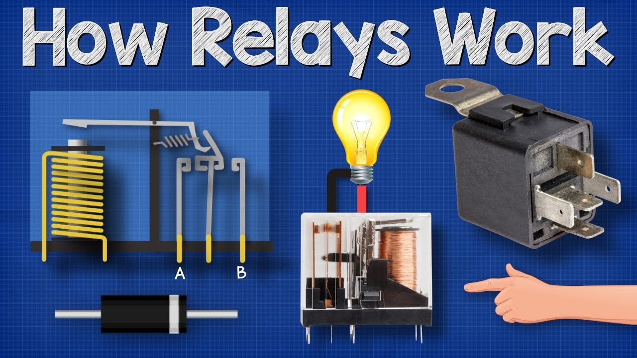
Further learning: How Relays Work — Basic Working Principle by The Engineering Mindset. The video explains the underlying concept; the project must still follow its own risk assessment and manufacturer documentation.
Często zadawane pytania
Co to jest przekaźnik elektromechaniczny?
Jest to przełącznik sterowany elektrycznie, który wykorzystuje cewkę, mechanizm magnetyczny i styki fizyczne do zmiany jednego lub większej liczby obwodów.
Co oznacza SPDT lub DPDT?
SPDT oznacza jeden biegun z dwoma przełączeniami; DPDT oznacza dwa takie bieguny obsługiwane razem. Zawsze sprawdzaj schemat wyprowadzeń producenta.
Dlaczego rodzaj obciążenia ma znaczenie?
Silniki, elektromagnesy, lampy, kondensatory i elektroniczne zasilacze mogą wykazywać prąd rozruchowy lub energię zgromadzoną, które bardzo różnią się od stałego obciążenia rezystancyjnego.
Kiedy gniazdo jest przydatne?
Gniazdo może uproszczać okablowanie i wymianę, ale wprowadza wymagania dotyczące wymiarów, parametrów znamionowych styków, siły trzymania i montażu, które muszą zostać zweryfikowane jako system.
Should every relay coil have a diode?
No. A diode is common for some DC coils, but polarity and slower release may be important. AC coils and other control objectives require different solutions.
Ostateczna reguła wyboru
Wybierz komponent tylko wtedy, gdy jego udokumentowane granice mechaniczne, elektryczne, środowiskowe, użyteczności i utrzymaniowe mieszczą się w całości w zmontowanym systemie. Jeśli jedna granica pozostaje nieznana, potraktuj ją jako otwarte pytanie inżynieryjne. Krótkie opóźnienie walidacji jest mniej kosztowne niż projektowanie wokół założenia, które pojawia się dopiero po instalacji.



