

Electromechanical relay selection requires separate checks for the coil circuit, contact circuit, mechanical format, environment, and failure behavior. Start with the control voltage and available coil drive, then define the real load—including inrush, inductive behavior, switching frequency, and required isolation. Choose the contact form, socket or mounting method, protection components, and replacement strategy only after those boundaries are clear. A relay’s headline current is not a universal permission to switch any load at that current.
Краткий ответ: Выбор — это системное решение. Согласуйте механический интерфейс, электрический интерфейс, условия окружающей среды, реакцию человека, план технического обслуживания и применимые стандарты. Приведенные ниже примеры являются руководством по принятию решений, а не универсальными рейтингами продукции.
Как работает устройство или система
When the coil is energized, its magnetic field moves an armature and changes one or more contacts. This allows a relatively low-power control signal to switch another circuit and can provide galvanic separation when the device is used within its ratings. De-energizing the coil returns a monostable relay to its normal position; latching versions behave differently. The coil is an inductive load and releases stored energy when switched off, so the drive circuit may need suppression. Suppression choice affects voltage stress and release time and must match AC or DC operation and the control design.

Критерии отбора с первого взгляда
| Область принятия решений | Что проверять | Почему это важно |
|---|---|---|
| Coil | Confirm nominal voltage, allowable range, AC/DC type, power, pickup, dropout, and drive capability | A nominal match alone does not prove reliable operation during supply tolerance or temperature change. |
| Contact form | Choose the required poles and NO, NC, or changeover arrangement | Use the de-energized state and failure strategy to define the circuit, not a familiar pin pattern. |
| Загрузить категорию | Identify resistive, inductive, capacitive, lamp, motor, or electronic load and its inrush | Contact life and permissible current can change greatly with load behavior. |
| Switching duty | Define operations per hour, expected life, bounce sensitivity, and release timing | Frequent operation may favor a different relay technology or derating strategy. |
| Isolation | Check coil-to-contact and contact-to-contact insulation requirements | System working voltage, pollution, wiring, PCB or socket design all contribute to the final insulation result. |
| Suppression | Coordinate coil suppression and load suppression with the control system | A diode, RC network, or varistor changes voltage stress and sometimes release speed; one solution does not fit every circuit. |
| Mechanical format | Verify plug-in socket, PCB, DIN adapter, retaining clip, dimensions, and terminal numbering | Serviceability and wiring errors depend on the complete relay-and-socket combination. |
| Окружающая среда | Review temperature, vibration, shock, dust, condensation, altitude, and corrosive atmosphere | Environmental stress can affect coil temperature, contacts, insulation, and mechanical operation. |
Таблица носит намеренно качественный характер. Числовые пределы должны браться из актуального технического описания для конкретной модели и из условий проектирования машины. Нельзя переносить значение из похожего продукта, другого напряжения, другой категории нагрузки или со страницы конкурента.
Как сделать выбор
Coil
Confirm nominal voltage, allowable range, AC/DC type, power, pickup, dropout, and drive capability This matters because a nominal match alone does not prove reliable operation during supply tolerance or temperature change. Record the chosen value, the source document, and the condition under which it applies. If the requirement cannot be verified from the current product documentation, keep it open for supplier confirmation rather than filling the gap with an assumption.
Contact form
Choose the required poles and NO, NC, or changeover arrangement This matters because use the de-energized state and failure strategy to define the circuit, not a familiar pin pattern. Record the chosen value, the source document, and the condition under which it applies. If the requirement cannot be verified from the current product documentation, keep it open for supplier confirmation rather than filling the gap with an assumption.
Загрузить категорию
Identify resistive, inductive, capacitive, lamp, motor, or electronic load and its inrush This matters because contact life and permissible current can change greatly with load behavior. Record the chosen value, the source document, and the condition under which it applies. If the requirement cannot be verified from the current product documentation, keep it open for supplier confirmation rather than filling the gap with an assumption.
Switching duty
Define operations per hour, expected life, bounce sensitivity, and release timing This matters because frequent operation may favor a different relay technology or derating strategy. Record the chosen value, the source document, and the condition under which it applies. If the requirement cannot be verified from the current product documentation, keep it open for supplier confirmation rather than filling the gap with an assumption.
Isolation
Check coil-to-contact and contact-to-contact insulation requirements This matters because system working voltage, pollution, wiring, PCB or socket design all contribute to the final insulation result. Record the chosen value, the source document, and the condition under which it applies. If the requirement cannot be verified from the current product documentation, keep it open for supplier confirmation rather than filling the gap with an assumption.
Suppression
Coordinate coil suppression and load suppression with the control system This matters because a diode, RC network, or varistor changes voltage stress and sometimes release speed; one solution does not fit every circuit. Record the chosen value, the source document, and the condition under which it applies. If the requirement cannot be verified from the current product documentation, keep it open for supplier confirmation rather than filling the gap with an assumption.
Mechanical format
Verify plug-in socket, PCB, DIN adapter, retaining clip, dimensions, and terminal numbering This matters because serviceability and wiring errors depend on the complete relay-and-socket combination. Record the chosen value, the source document, and the condition under which it applies. If the requirement cannot be verified from the current product documentation, keep it open for supplier confirmation rather than filling the gap with an assumption.
Окружающая среда
Review temperature, vibration, shock, dust, condensation, altitude, and corrosive atmosphere This matters because environmental stress can affect coil temperature, contacts, insulation, and mechanical operation. Record the chosen value, the source document, and the condition under which it applies. If the requirement cannot be verified from the current product documentation, keep it open for supplier confirmation rather than filling the gap with an assumption.

Рассмотрение заявки
Используйте следующие сценарии в качестве подсказок для инженерной экспертизы. Сами по себе они не определяют пригодность:
- Interface a plc output with a field circuit after coil-drive limits are confirmed. During commissioning, verify the command, expected response, abnormal response, and reset behavior in the assembled machine.
- Switch several isolated contact signals from one control command. During commissioning, verify the command, expected response, abnormal response, and reset behavior in the assembled machine.
- Provide a replaceable plug-in interface for maintenance-friendly control panels. During commissioning, verify the command, expected response, abnormal response, and reset behavior in the assembled machine.
- Use interposing contacts to separate control-system and machine-circuit responsibilities. During commissioning, verify the command, expected response, abnormal response, and reset behavior in the assembled machine.
- Select a different technology when switching frequency, silent operation, or lifetime requirements exceed electromechanical capability. During commissioning, verify the command, expected response, abnormal response, and reset behavior in the assembled machine.
Для каждого случая следует предусмотреть предельные значения допусков, пуск, выключение, потерю питания, восстановление питания, режим технического обслуживания, предсказуемое неправильное использование и замену компонентов. Если команда затрагивает безопасность персонала, защитная функция должна быть разработана и проверена независимо от обычного технологического управления.
Ввод в эксплуатацию и проверка
- Зафиксировать требование. Опишите предполагаемое состояние, действия оператора, нагрузку, питание, окружающую среду и время отклика простым языком.
- Проверьте точную модель. Сопоставьте код заказа с его текущим чертежом, таблицей номиналов, схемой выводов и инструкциями.
- Осмотрите установку. Подтвердите вырез, крепеж, выравнивание, ввод кабеля, задний зазор, снятие натяжения и защиту токоведущих частей.
- Тест нормального функционирования. Используйте устройство во всем ожидаемом диапазоне движения, для всех пользователей, при различных нагрузках и условиях окружающей среды.
- Проверка нештатных условий. Включите оборванный провод, заклинивший механизм, прекращение подачи питания, загрязнение и другие неисправности, выявленные в ходе оценки рисков.
- Записать результаты. Сохраните модель, версию, метод испытания, дату, критерии приемки, измеренные наблюдения и утверждающего лица.
- Запланируйте периодические проверки. Основывайте интервалы осмотра и замены на режиме работы, условиях окружающей среды, степени критичности и наблюдаемом износе, а не на вымышленном универсальном графике.
Типичные ошибки при отборе
- Choosing from contact current alone while ignoring load category and inrush. Предотвратите это, назначив ответственного, зарегистрировав применимый чертеж или техническое описание и проверив фактическую установку вместо того, чтобы полагаться на название продукта или изображение из каталога.
- Driving a dc coil without considering turn-off transient protection. Предотвратите это, назначив ответственного, зарегистрировав применимый чертеж или техническое описание и проверив фактическую установку вместо того, чтобы полагаться на название продукта или изображение из каталога.
- Adding a suppression diode without checking its effect on release time. Предотвратите это, назначив ответственного, зарегистрировав применимый чертеж или техническое описание и проверив фактическую установку вместо того, чтобы полагаться на название продукта или изображение из каталога.
- Assuming identical-looking plug-in relays share the same pinout. Предотвратите это, назначив ответственного, зарегистрировав применимый чертеж или техническое описание и проверив фактическую установку вместо того, чтобы полагаться на название продукта или изображение из каталога.
- Mixing safety and ordinary control functions without the required architecture. Предотвратите это, назначив ответственного, зарегистрировав применимый чертеж или техническое описание и проверив фактическую установку вместо того, чтобы полагаться на название продукта или изображение из каталога.
- Placing the relay in a hot enclosure without checking coil and contact derating. Предотвратите это, назначив ответственного, зарегистрировав применимый чертеж или техническое описание и проверив фактическую установку вместо того, чтобы полагаться на название продукта или изображение из каталога.
Что включить в запрос поставщику
Полезный запрос должен содержать информацию о применении, целевом рынке, применимых стандартах, параметрах питания и нагрузки, интерфейсе управления, чертеже механической части, размерах панели или монтажных размерах, способе подключения кабелей, условиях окружающей среды, предполагаемой частоте работы, количестве и необходимой документации. Добавьте фотографии или эскиз движения, если способ установки приводного механизма или принцип работы оператором трудно описать словами. Попросите поставщика указать сделанные допущения и исключения. Для новой или измененной конструкции получите образцы и проведите полную валидацию перед размещением серийного заказа.
ONPOW предоставляет ONPOW industrial relay products в своем более широком ассортимент продукции для промышленного управления. Используйте страницы продуктов для определения возможных семейств, а затем уточните конкретную модель в соответствии с актуальной технической информацией и условиями вашего проекта.
Связанное чтение ONPOW
Авторитетные источники
Обучающее видео
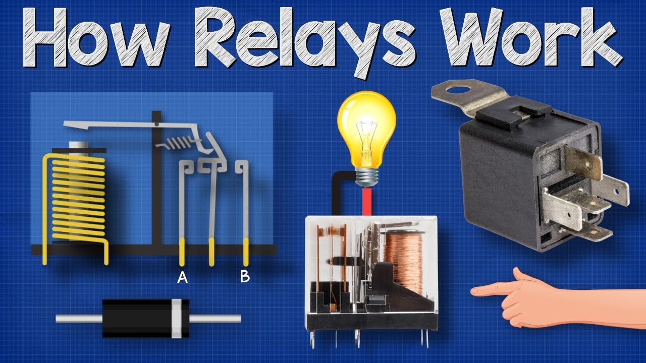
Further learning: How Relays Work — Basic Working Principle by The Engineering Mindset. The video explains the underlying concept; the project must still follow its own risk assessment and manufacturer documentation.
Часто задаваемые вопросы
Электромеханическое реле — это электрическое устройство, использующее электромагнит для механического замыкания или размыкания контактов.
Это электрически управляемый переключатель, который использует катушку, магнитный механизм и физические контакты для коммутации одной или нескольких цепей.
Что означает SPDT или DPDT?
СПДТ (однополюсный переключатель на два направления) описывает один полюс с двумя направлениями; ДПДТ описывает два таких полюса, управляемых совместно. Всегда проверяйте схему выводов производителя.
Почему тип нагрузки имеет значение?
Двигатели, соленоиды, лампы, конденсаторы и электронные источники питания могут иметь пусковой или накопленный ток (энергию), который существенно отличается от стабильной резистивной нагрузки.
Когда полезен сокет?
Гнездо может упростить монтаж и замену, но добавляет габариты, номиналы выводов, требования к фиксации и установке, которые необходимо проверять как единую систему.
Should every relay coil have a diode?
No. A diode is common for some DC coils, but polarity and slower release may be important. AC coils and other control objectives require different solutions.
Правило окончательного отбора
Выбирайте компонент только тогда, когда все его документированные механические, электрические, экологические границы, а также границы удобства использования и обслуживания соответствуют собранной системе. Если хотя бы одна граница остается неизвестной, рассматривайте это как открытый инженерный вопрос. Краткая задержка на валидацию обходится дешевле, чем проектирование с учетом допущения, которое обнаруживается только после установки.



