

As industrial automation continues to expand, push button switch wiring has become an important topic for equipment manufacturers, control panel builders, and maintenance engineers. Push button switches are widely used in machine control, electrical cabinets, conveyor systems, motor control circuits, and PLC-based automation systems. With the growing demand for safer, more reliable, and easier-to-install control components, buyers are paying more attention to correct wiring, product durability, and long-term operating stability.The market is moving toward modular design, compact panel installation, LED indication, waterproof protection, and compatibility with 24V DC control systems. In many industrial applications, push button switches are no longer simple on/off components. They are part of a complete control system that may include contactors, relays, PLC inputs, emergency stop circuits, and signal indicators.Customers need push button switches because they provide a direct and reliable way to control equipment operation. Whether used for start, stop, reset, mode selection, fault indication, or emergency shutdown, a properly selected switch helps improve operator safety and machine control efficiency.However, buyers often have concerns before purchasing. Common questions include whether the switch voltage matches the control circuit, whether the contact rating is suitable, whether the product can withstand dust or moisture, and whether the wiring terminals are easy to identify. For OEMs and industrial projects, buyers may also care about mounting size, certifications, mechanical life, customization options, and stable batch supply.
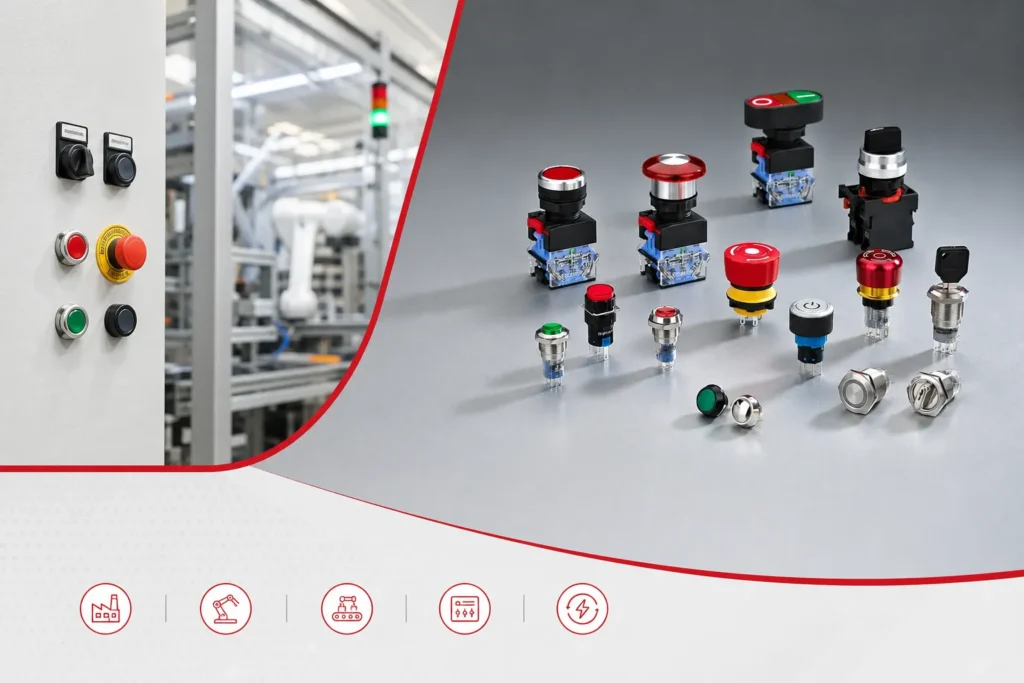
What Is a Push Button Switch?
A push button switch is a manually operated electrical switch used to open or close a control circuit. When the operator presses the button, the internal contact changes state and sends a signal to the connected circuit.
In industrial equipment, push button switches are commonly used for:
- Machine start and stop control
- Emergency stop functions
- Reset commands
- PLC signal input
- Indicación de encendido
- Fault alarm indication
- Manual control panel operation
Note: Depending on the design, a interruptor de botón may include NO contacts, NC contacts, LED indicators, contact blocks, metal housings, plastic housings, or waterproof structures.
How Does a Push Button Switch Work?
A push button switch works by changing the state of its internal electrical contacts. When the button is pressed, the actuator moves the contact mechanism and either closes or opens the circuit.
For example, a normally open contact closes when pressed, allowing current or signal to pass through. A normally closed contact opens when pressed, interrupting the circuit.
In industrial control circuits, the push button usually sends a low-voltage control signal, such as 24V DC, to a relay, contactor coil, or PLC digital input. This allows the switch to control larger equipment indirectly and safely.
Control Circuit: A low-power electrical circuit used to control relays, contactors, PLC inputs, or other industrial devices.
Normally Open vs Normally Closed Contacts
Comprensión NO y NC contacts is essential before wiring a push button switch.
Normally Open Contact
A normally open contact is open in its default state. The circuit is disconnected when the button is not pressed. When the button is pressed, the contact closes and the circuit becomes connected.
NO contacts are commonly used for:
- Botones de inicio
- Botones de reinicio
- Signal input buttons
- PLC input commands
Normally Open Contact, NO: A contact that remains open in its normal state and closes only when the push button is pressed.
Normally Closed Contact
A normally closed contact is closed in its default state. The circuit is connected when the button is not pressed. When the button is pressed, the contact opens and interrupts the circuit.
NC contacts are commonly used for:
- Stop buttons
- Pulsadores de parada de emergencia
- Safety control circuits
- Interlock circuits
Normally Closed Contact, NC: A contact that remains closed in its normal state and opens when the push button is pressed.
| Contact Type | Default State | State When Pressed | Common Application |
|---|---|---|---|
| NO | Abierto | Cerrado | Start, reset, signal input |
| NC | Cerrado | Abierto | Stop, emergency stop, safety circuit |
| NO + NC | One open, one closed | Both change state | Combined control or feedback circuits |
In many motor control circuits, the start button uses NO contact, while the stop button uses NC contact. This design helps improve operational safety and circuit reliability.
Types of Push Button Switches Used in Industrial Applications
Interruptor de botón pulsador momentáneo
A momentary push button switch only changes state while it is being pressed. Once the operator releases the button, it returns to its original state.
It is commonly used for start control, stop control, reset functions, jog operation, and PLC input signals. This type is widely used in industrial control panels because it provides short and clear command signals.
Maintained / Latching Push Button Switch
A maintained push button switch keeps its state after being pressed. The operator usually needs to press it again to return it to the original position.
It is suitable for power on/off control, mode selection, lighting control, and manual enable or disable functions.
Illuminated Push Button Switch
An illuminated push button switch includes an LED or lamp indicator. It can provide visual feedback on the control panel.
Common applications include power indication, machine running status, fault alarm signal, operation confirmation, and panel position indication.
When wiring an illuminated push button, it is important to confirm the lamp voltage, such as 12V DC, 24V DC, 110V AC, or 220V AC. For DC LED types, polarity must also be checked.
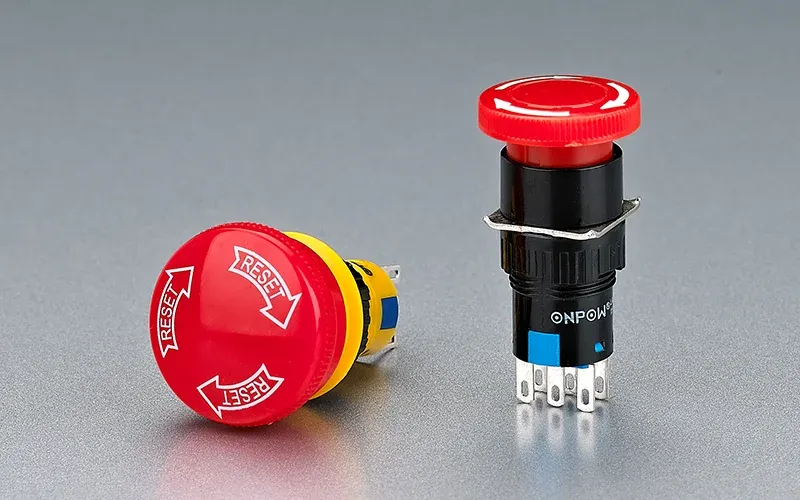
Pulsador de parada de emergencia
An emergency stop push button is used to stop machinery immediately in dangerous situations. It usually has a red mushroom head design and is often installed in a visible and accessible position.
In industrial safety circuits, emergency stop buttons commonly use NC contacts. When the button is pressed or if the wire is broken, the circuit opens and the machine stops. This design helps improve fail-safe performance.
Interruptor de botón pulsador de metal
Metal push button switches are often used in harsh industrial environments. They usually have stainless steel, nickel-plated brass, or aluminum alloy housings.
Their advantages include higher mechanical strength, better impact resistance, premium appearance, good corrosion resistance, and optional waterproof protection such as IP65 or IP67.
Selector Switch and Key Switch
Selector switches and key switches are often used together with push buttons in industrial panels. Selector switches are commonly used for manual/automatic mode selection, forward/reverse control, speed mode selection, and local/remote control switching.
Key switches are used when access control or operational permission is required, such as maintenance mode or safety lock control.
Push Button Switch Terminal Identification
Before wiring, it is important to identify the terminals correctly. Different manufacturers may use different markings, but the basic logic is similar.
| Terminal Marking | Meaning | Descripción |
|---|---|---|
| COM | Terminal común | Shared input terminal for contact circuit |
| NO | Normally open | Closes when button is pressed |
| NC | Normally closed | Opens when button is pressed |
| + / – | LED polarity | Used for DC illuminated buttons |
| A1 / A2 | Lamp terminal | Often used for indicator lamp connection |
| 13 / 14 | NO contact | Standard marking for normally open contact |
| 21 / 22 | NC contact | Standard marking for normally closed contact |
For illuminated push buttons, the contact terminals and LED terminals may be independent. Always check the wiring diagram or product marking before installation.
Push Button Switch Wiring Diagram Explained
A push button switch wiring diagram shows how the switch terminals connect to the power supply, load, control circuit, PLC input, relay, or contactor.
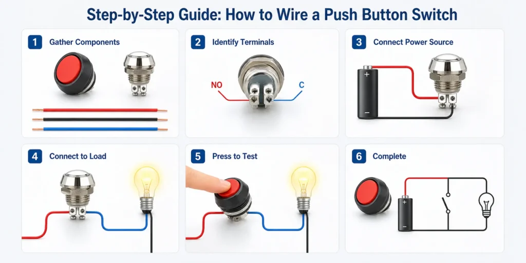
Basic NO Push Button Wiring
In a basic NO wiring circuit, the power or signal line enters the COM terminal, and the output wire is connected to the NO terminal. When the button is pressed, COM and NO are connected.
This wiring is suitable for start signal, reset signal, PLC digital input, and relay triggering. For example, in a 24V DC PLC input circuit, pressing the NO button sends a 24V signal to the PLC input terminal.
Basic NC Push Button Wiring
In a basic NC wiring circuit, the power or signal line enters the COM terminal, and the output wire is connected to the NC terminal. The circuit remains closed in the normal state and opens when the button is pressed.
This wiring is suitable for stop signal, emergency stop circuit, safety interlock, and machine protection circuit.
Start/Stop Push Button Wiring with Contactor
In industrial motor control, push buttons are often wired with a contactor. The start button uses a NO contact, and the stop button uses a NC contact.
- The stop button is connected in series with the control circuit.
- The start button sends power to the contactor coil when pressed.
- The auxiliary contact of the contactor creates a self-holding circuit.
- When the stop button is pressed, the circuit opens and the contactor coil is de-energized.
This structure is commonly used for motors, pumps, fans, conveyors, and other industrial loads.
Contactor: An electrically controlled switching device commonly used to control motors, pumps, fans, and other high-power industrial loads.
LED Push Button Switch Wiring
An LED push button switch may be wired in different ways depending on the required indication function.
- LED always on: Used as panel position or power indication.
- LED on when pressed: Used as operation feedback.
- LED on when equipment is running: Connected through a relay, PLC output, or contactor auxiliary contact.
When wiring LED buttons, always confirm whether the lamp is designed for AC or DC voltage. For DC LEDs, incorrect polarity may prevent the lamp from lighting.
Push Button Wiring with PLC Input
In automation systems, push buttons are often connected to PLC digital input modules. The switch sends a control signal to the PLC, and the PLC program controls the output device.
- PLC input voltage, commonly 24V DC
- PNP or NPN input type
- NO or NC contact requirement
- Common terminal wiring
- Input filtering and signal stability
For start signals, NO contacts are commonly used. For stop or safety-related signals, NC contacts are often preferred.
PLC Digital Input: A PLC input terminal that receives on/off signals from devices such as push button switches, sensors, and limit switches.
Step-by-Step Guide: How to Wire a Push Button Switch
Step 1: Turn Off the Power
Before installation, disconnect the power supply completely. Use a voltage tester to confirm that the circuit is de-energized. This is essential for operator safety.
Step 2: Check the Switch Rating
Check the rated voltage, rated current, contact capacity, LED voltage, and AC/DC type. The switch rating must match the control circuit requirements.
If the switch is used in a high-power system, it should control a relay or contactor instead of directly switching the load.
Step 3: Identify the Terminals
Confirm the terminal markings such as COM, NO, NC, +, -, A1, A2, 13/14, or 21/22. For multi-contact push buttons, make sure each contact block is correctly identified.
Step 4: Prepare the Panel Opening
Check the mounting hole size, such as 16mm, 19mm, 22mm, 25mm, or 30mm. For industrial control cabinets, 22mm push buttons are very common.
Install the sealing gasket properly if the switch has waterproof protection.
Step 5: Connect the Wires
Connect the wires according to the wiring diagram. Use suitable wire size, insulated terminals, and proper crimping tools. Make sure the terminal screws are tightened securely.
Avoid exposed copper wires, loose connections, or crossed wiring.
Step 6: Test the Circuit
After wiring, test the switch function before full operation. Check whether the NO and NC contacts work correctly, whether the LED lights properly, and whether the equipment starts or stops as expected.
Step 7: Final Inspection
Inspect the panel installation, wiring tightness, insulation, grounding, and waterproof sealing. Make sure the button operates smoothly and returns or latches correctly.
Common Push Button Switch Wiring Mistakes
Confusing NO and NC Contacts
A common mistake is wiring the start button to NC or wiring the stop button to NO. This can cause incorrect machine operation or safety risks.
Using the Wrong LED Voltage
For illuminated push buttons, the LED voltage must match the power supply. For example, a 24V LED cannot be directly connected to 220V AC unless it is designed for that voltage.
Overloading the Switch Contact
Small push button contacts are not designed to switch large motor loads directly. In industrial applications, they should normally control a relay, contactor, or PLC input.
Loose Wiring or Poor Terminal Contact
Loose terminals can cause intermittent signals, voltage drop, overheating, or equipment failure. All wiring should be tightened and checked during maintenance.
Ignoring IP Rating
For dusty, humid, or outdoor environments, IP65 or IP67 push button switches are commonly selected to improve protection against dust and water ingress. The IP code system is defined by IEC 60529 Ingress Protection Ratings, which classifies the degree of protection provided by electrical enclosures and devices.
IP Rating: A protection rating defined by IEC 60529 that indicates resistance to dust and water ingress.
Wrong Mounting Hole Size
If the mounting hole does not match the switch size, the button may not be fixed properly. This can affect operation, sealing, and panel appearance.
Troubleshooting Push Button Switch Problems
When a pulsador switch does not work correctly, the issue is often related to wiring, contact type, voltage, or mechanical installation.
Common problems include:
- Button does not respond
- LED does not light
- Equipment cannot start
- Equipment cannot stop
- Switch becomes hot
- Circuit breaker trips
- Signal is unstable
Basic troubleshooting steps:
- Check whether the power supply is correct.
- Confirm COM, NO, and NC terminals.
- Test the contact with a multimeter.
- Check LED voltage and polarity.
- Inspect terminal tightness.
- Check whether the contact rating is overloaded.
- Confirm PLC or relay input logic.
If the switch is mechanically damaged or the contact resistance is abnormal, replacement is recommended.
How to Choose the Right Push Button Switch for Industrial Equipment
Selecting the right push button switch depends on the electrical circuit, installation environment, machine function, and safety requirements.
Mounting Hole Size
Common mounting sizes include 12mm, 16mm, 19mm, 22mm, 25mm, and 30mm. For many industrial control panels, 22mm is a standard and widely used size.
Operation Type
- Momentary: Start, stop, reset
- Maintained: Power control or function enable
- Mushroom head: Emergency stop
- Key switch: Access control
- Selector switch: Mode selection
Contact Configuration
Common contact configurations include 1NO, 1NC, 1NO1NC, and 2NO2NC. For more complex control circuits, modular contact blocks allow flexible combinations.
Voltage and Current Rating
Check both contact rating and LED voltage. Common industrial control voltages include 12V DC, 24V DC, 110V AC, 220V AC, and 380V AC. In automation systems, 24V DC is widely used for control signals.
Material and Head Type
Plastic push buttons are cost-effective and suitable for general panels. Metal push buttons provide better durability and are suitable for harsh environments.
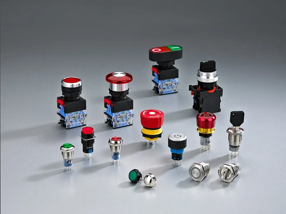
Common head types include flat head, raised head, mushroom head, ring illuminated type, power symbol type, and key lock type.
Grado de protección IP
For indoor control cabinets, basic protection may be enough. For outdoor, dusty, or humid environments, choose waterproof and dustproof types.
- IP40 for general indoor use
- IP65 for dust and water spray protection
- IP67 for higher waterproof requirements
Certifications and Standards
For industrial projects, certifications and compliance standards are important factors when selecting push button switches. Depending on the target market and application, buyers may require CE compliance, UL recognition, RoHS compliance, or IEC-related standards. These certifications help verify product safety, material compliance, and suitability for electrical control applications.
Push Button Switch Applications in Industrial Control
Push button switches are used in many industrial systems where reliable manual operation is required.
- Control cabinets
- Automation equipment
- Máquinas CNC
- Sistemas de transporte
- Packaging machines
- Pump control panels
- HVAC systems
- Power distribution panels
- Outdoor electrical equipment
- Marine and transportation equipment
In these applications, push buttons are often used together with contactors, relays, indicators, alarms, terminal blocks, PLC modules, and control transformers.
Why Choose Hongbo Push Button Switch Solutions
We provide push button switch solutions designed for industrial control and equipment manufacturing applications. Our product range covers metal push buttons, plastic push buttons, illuminated push buttons, emergency stop buttons, selector switches, key switches, and customized panel switch solutions.Our products are designed for stable operation, long mechanical life, reliable contact performance, and easy panel installation. Multiple options are available for mounting size, contact configuration, LED color, voltage, head style, and protection level.We can also support OEM and project requirements, including custom symbols, wiring harnesses, connectors, logo marking, and control panel matching solutions.For equipment manufacturers, control cabinet builders, automation system integrators, and industrial distributors, we offer reliable product selection support and flexible supply capabilities.
Preguntas Frecuentes
1. How do you wire a push button switch?
To wire a push button switch, first turn off the power and identify the terminals, such as COM, NO, NC, +, and -. For a basic start button, connect the power or signal wire to COM and the output wire to NO. When the button is pressed, the circuit closes and sends a signal to the load, relay, contactor, or PLC input.
2. What is the difference between NO and NC on a push button switch?
NO means normally open, and the circuit is open when the button is not pressed. It closes when you press the button. NC means normally closed, and the circuit is closed when the button is not pressed. It opens when you press the button. In most industrial circuits, NO is used for start, while NC is used for stop or emergency stop.
3. How do I wire a 4-pin push button switch?
A 4-pin push button switch usually has two terminals for the switch contact and two terminals for the LED lamp. The switch terminals are used for circuit control, while the LED terminals are connected to the correct lamp voltage, such as 12V, 24V, 110V, or 220V. Always check the wiring diagram because different manufacturers may use different pin layouts.
4. How do I wire a 5-pin LED push button switch?
A 5-pin LED push button switch often includes COM, NO, NC, LED positive, and LED negative terminals. Connect COM and NO for a normally open start function, or COM and NC for a normally closed stop function. Then connect the LED terminals to the correct power supply. For DC LED models, make sure the polarity is correct.
5. Can a push button switch control a motor directly?
In most industrial applications, a push button switch should not control a motor directly. The better method is to use the push button to control a contactor, relay, or PLC input. This protects the switch contacts and allows the control circuit to safely manage higher-power loads such as motors, pumps, fans, and conveyors.
6. Why does my LED push button switch not light up?
If the LED does not light up, the most common reasons are wrong voltage, reversed polarity, incorrect LED terminal connection, or a damaged lamp. For example, a 24V LED push button will not work correctly if connected to the wrong voltage. For DC types, check the + and – terminals before powering the circuit.
7. What size push button switch is commonly used in control panels?
The 22mm push button switch is one of the most common sizes used in industrial control panels and electrical cabinets. Other common mounting sizes include 16mm, 19mm, 25mm, and 30mm. The right size depends on the panel design, installation space, and equipment standard.
8. What is the best push button switch for outdoor or wet environments?
For outdoor, dusty, humid, or washdown environments, choose a waterproof push button switch with a suitable IP rating, such as IP65 or IP67. Metal push button switches with stainless steel housings are often preferred for harsh environments because they offer better durability, corrosion resistance, and sealing performance.
Push button switches are essential components in industrial control systems. Correct wiring requires a clear understanding of NO and NC contacts, terminal markings, LED voltage, contact ratings, and installation conditions.For industrial equipment, the right push button switch should be selected according to the control function, mounting size, electrical rating, IP protection level, material, and safety requirements. A properly selected and correctly wired switch can improve machine reliability, operator safety, and control panel performance.
Referencias
International Federation of Robotics, “Industrial Robots and Automation Market Information.”
International Electrotechnical Commission, “IEC 60529 Ingress Protection Ratings.”



