

An inquiry for a 3/8 inch push button switch should begin with the mechanical drawing, not with a diameter conversion alone. Three-eighths of an inch is 0.375 in, or 9.525 mm, but that number does not tell you whether a listing refers to a panel opening, a threaded shank, or another feature. Confirm the manufacturer’s drawing before a panel is drilled or a replacement is ordered.

Part 1. Read the 3/8-inch label before choosing a hole
The phrase “3/8 inch push button switch” is a useful starting phrase, but it is not a complete installation instruction. In catalogue language, the number can describe the part of the operator that passes through a panel, a thread family, or the recommended mounting opening. Those are related dimensions, yet they are not interchangeable.
Treat the listing as a question to resolve. Ask for the dimensioned outline drawing and identify the callout attached to 3/8. A suitable metal operator must also match the panel material, thickness, fastening hardware, terminal clearance, and intended control circuit.
| If the 3/8 label describes | What to request on the drawing | Purchasing consequence |
|---|---|---|
| Panel cutout | Nominal opening, tolerance, and edge condition | Machine the specified opening only. |
| Threaded shank | Thread designation, pitch, and usable length | Confirm the nut and panel-thickness stack. |
| Body or bezel | Outside diameter and flange clearance | Check adjacent operators and legend space. |
| Informal nominal size | A labelled sectional drawing | Do not release the panel for machining. |
For panels with compact layouts, a metric family may be the better documented choice. The 8 mm push button switch selection guide explains a separate small-cutout route; it is not evidence that an 8 mm part fits a 3/8-inch opening.
Part 2. Convert 3/8 in without converting it into a product specification
Using the standard conversion, 3/8 in equals 9.525 mm. This is helpful when a drawing uses millimetres while a legacy bill of materials uses inches. It is not permission to round a required opening to 9.5 mm, 10 mm, or another convenient drill size.
Important : A unit conversion expresses length; it does not define a mounting tolerance, thread, or approved panel cutout. Use the NIST length-unit reference for conversion context, then use the selected manufacturer drawing for the machining instruction.
A 10 mm product family can look close numerically but may have a different thread, nut geometry, locating feature, or specified tolerance. Equally, a 3/8-threaded component can require a mounting arrangement that does not match a nominal 9.525 mm hole. The safe decision is always drawing first, then tooling.
| Dimension statement | What it proves | What it does not prove |
|---|---|---|
| 3/8 in = 9.525 mm | A mathematical conversion | The correct drill, punch, or thread |
| “Fits 3/8 hole” | A supplier fit claim | Panel tolerance or stack-up limits |
| “3/8-32 thread” | A thread designation | The electrical contact arrangement |
| “10 mm mounting” | A stated metric family | Compatibility with a 3/8-in listing |
If the panel already has a metric hole pattern, compare the dimensional drawing rather than guessing from a nominal label. Our 8 mm vs 10 mm push button guide can help frame those two metric families after the original hole dimension is known.
Part 3. Separate cutout, shank, and thread callouts
The panel cutout is the opening in the enclosure. The shank is the portion of an operator that passes through that opening. A thread callout describes the fastening interface.
A bezel or head diameter can be larger than all of these, so it also needs space around the hole.
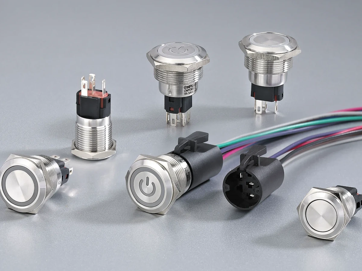
Read each dimension alongside its leader line and section view. The Rockwell Automation note on pushbutton diameter measurement is a useful reminder that diameter labels need a defined reference point. It does not replace the selected product drawing.
The installation hardware deserves the same attention. Check whether a gasket sits between bezel and panel, whether an anti-rotation feature needs a notch, and whether the retaining nut can be tightened with the planned tool. A drawing that shows only the front view is rarely enough for a first article build.
Part 4. Review the panel drawing before machining
Before releasing sheet metal, review one controlled drawing revision with the operator supplier and the panel fabricator. Include the opening, tolerance, panel thickness, surface treatment, and any obstruction on both sides of the panel. This prevents a correct-looking component from becoming a late rework issue.
| Drawing field to send | Pourquoi c'est important | Risk if omitted |
|---|---|---|
| Cutout diameter and tolerance | Sets the punch or drill requirement | Loose fit, interference, or rework |
| Panel thickness and material | Determines usable shank and nut engagement | Insufficient fastening range |
| Section view behind the door | Reveals terminals, wiring, and brackets | Rear collision after assembly |
| Front layout and spacing | Checks bezel and legend clearance | Crowded controls or hidden labels |
| Required operation and contact need | Aligns the selected operator to the circuit | A mechanically fitting but unsuitable item |
Do not rely on a web thumbnail for these fields. IEC 60947-5-1 covers the general field of low-voltage control-circuit devices, while the exact mounting interface remains a product-drawing decision. For a wider panel arrangement check, see the push-button control panel layout guide.
Part 5. Check rear clearance and the fastening stack
Rear clearance is more than the depth of the push button. Allow for terminals, wire bend radius, connectors, protective boots, brackets, and a tool path to fit or remove the retaining nut. Also check that the door can close without the body touching a component mounted behind it.
The fastening stack should be evaluated at the minimum and maximum panel thickness permitted by the drawing. Paint, labels, films, and sealing washers change the stack height. If the application needs environmental sealing, confirm the specific SKU’s gasket arrangement and applicable rating rather than assuming that a metal head seals every installation.
A small pilot hole is not a substitute for a controlled production process. Choose the punch, drill, or machining method that can achieve the documented tolerance and burr condition. Keep the drawing, sample approval, and revised bill of materials together so an enclosure revision does not silently change the fit.
Part 6. Route a documented requirement to ONPOW metal push buttons
After the opening and rear space are documented, use the ONPOW metal push button switch category as an enquiry route for suitable product families. It should not be read as an assertion that every category item is an exact 3/8-inch fit. Confirm the selected SKU’s mounting drawing, operation, contact configuration, illumination option, terminal arrangement, and any requested documentation.
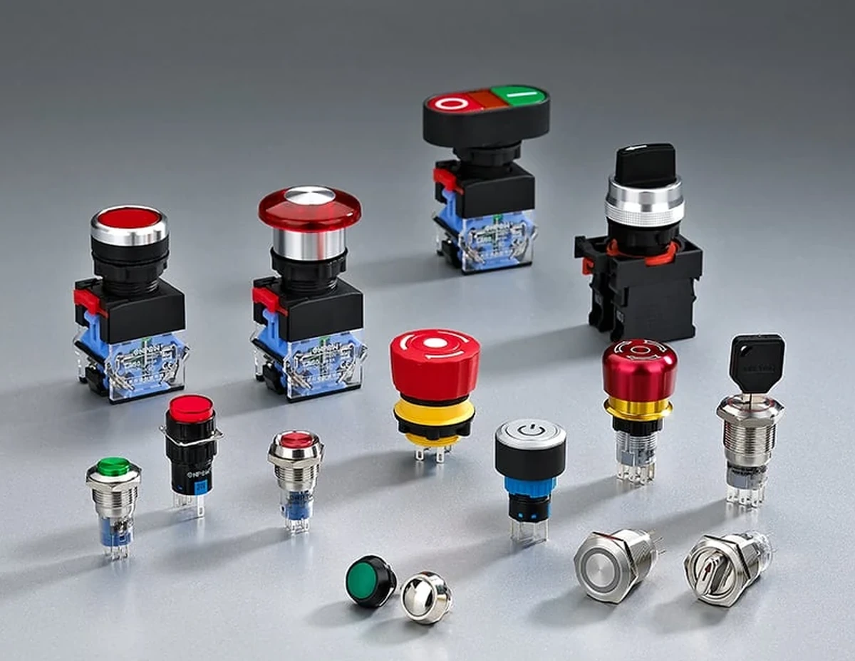
Send the controlled panel drawing, annual or project quantity, destination, operating function, and required lead time to the ONPOW sales team. State whether 3/8 refers to an existing opening, a thread, or a legacy part description. That single clarification makes technical review much faster and avoids treating a nominal label as a complete specification.
For an RFQ, attach those inputs to the drawing review so the mounting and product configuration can be checked together.
For other installation and sourcing topics, browse the ONPOW Blog. The most reliable outcome is a written confirmation against the final drawing before production tooling is used.
Questions Fréquemment Posées
Is 3/8 inch exactly the same as a 10 mm push button switch?
No. Three-eighths of an inch is 9.525 mm, whereas 10 mm is a different nominal size. The drawing must confirm the cutout, thread, tolerance, and fastening arrangement before treating either as a replacement.
What hole should I drill for a 3/8 inch push button switch?
Use the selected manufacturer’s mounting-hole callout and tolerance. Do not drill a 9.5 mm hole only because 3/8 converts to 9.525 mm.
Can a 3/8 label refer to the threaded shank?
Yes, listings can use an imperial label for a threaded shank or thread family. Read the full thread designation and sectional drawing, not just the headline diameter.
Does a larger shank mean a higher electrical rating?
No. Mechanical size does not establish the contact duty, utilization conditions, or circuit suitability. Confirm those fields separately on the selected product documentation.
What rear-clearance information should I provide?
Provide a section view showing panel thickness, nearby brackets, wiring space, terminal direction, and door-close clearance. Include the planned wire and connector arrangement where it affects space.
Can ONPOW supply a 3/8 inch push button switch?
Use the metal push-button category as a product-family enquiry route and submit the drawing. ONPOW should confirm the selected SKU’s mounting dimensions rather than relying on a nominal 3/8-inch description.



