

Choose a 12V micro switch for the actual DC circuit, not simply because a listing includes the number 12V. A conventional mechanical micro switch is a dry contact: the surrounding circuit supplies the voltage. For a control input, verify the contact’s suitability for the input current and voltage, minimum switching conditions, terminal arrangement, mechanical actuation, and environment. A contact that can switch a larger load may still need separate confirmation for a small electronic signal. Keep a 12V sensing circuit distinct from a 12V motor, solenoid, or lamp circuit, because their switching demands are different.
First identify what the 12V circuit does
Write down whether the switch reports position to an electronic input or directly controls a load. A PLC or embedded-controller input can draw a small current; a relay coil or actuator can impose inductive switching stress. Both circuits may use a nominal 12V supply, but they do not require the same contact assessment.
Identify the source of the voltage, the return path, the receiving device, and the expected closed-contact current. Check the supply’s allowed variation and the receiving input’s thresholds. A regulated 12V bench supply and a noisy equipment supply are not necessarily equivalent electrical environments.
For the mechanism, read how a micro switch works. For the system-level choice, use industrial micro switch selection. This article focuses on low-voltage DC input service rather than power switching.
A dry contact has no universal positive terminal
The COM terminal is common to the moving-contact arrangement. It is not inherently the supply’s positive connection or the circuit ground. NO and NC describe contact paths in the defined normal actuator position. The equipment drawing determines which terminal receives a supply or reference and which goes to the input.
A conventional contact may complete a sourcing or sinking input circuit if that arrangement is permitted by the input module. Confirm the receiver manual and wiring diagram. Do not copy a connection from another controller simply because its supply is also 12V.
| Circuit question | Information to obtain | Pourquoi c'est important |
|---|---|---|
| Supply conditions | Nominal value and allowed operating range | Input thresholds and transient exposure |
| Closed-contact current | Actual current through the selected path | Minimum-load and contact suitability |
| Receiver interface | Sourcing, sinking, reference, input thresholds | Correct signal polarity and wiring |
| Contact arrangement | Exact COM, NO, NC drawing | Intended normal and operated states |
| Electrical environment | Noise sources and cable route | False transitions and interface protection |
| Mechanical motion | Force, travel, direction, reset | Reliable physical state detection |
The table is a specification checklist, not a terminal map or a set of universal 12V ratings.
Check low-level switching capability explicitly
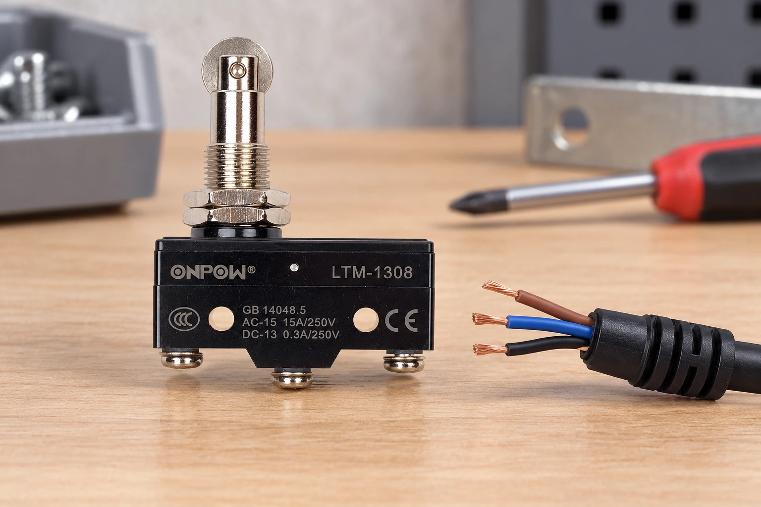
For a small electronic input, ask whether the manufacturer declares an appropriate minimum switching voltage or current and contact material. Surface films, contamination, and contact construction can affect low-level operation. A prominent ampere rating for a heavier load does not answer this question.
Do not invent a minimum current from a generic micro-switch article. Different contact options can have different intended service. Obtain the data for the precise model and suffix, and compare it with the actual input current. If the manufacturer does not provide enough information, keep the selection pending or use a documented interface suitable for the application.
An isolated continuity test can identify a contact state, but it does not simulate long-term service at the receiving input’s current. A beeping meter cannot establish an electrical-life rating or prove immunity to a contaminated installation. Test the full intended circuit through the approved qualification plan.
Keep signal switching separate from DC load switching
A 12V motor can draw substantial current, including starting or stalled current. A solenoid or relay coil can generate a turn-off transient. A lamp can have an inrush characteristic. These effects are not captured by the nominal supply voltage alone.
If the micro switch only needs to indicate position, use an appropriate control input and let a suitably rated device handle the load. The interface must still be designed for the machine: contact or transistor output, input protection, suppression, and response time all need review. Adding a relay is not an automatic approval of the circuit.
Le IEC 60947-5-1 publication identifies the standards scope for electromechanical control circuit devices. Its published scope does not assign a DC rating or minimum-load capability to every switch. Request those model-specific characteristics rather than treating a general standards reference as a product specification.
Choose NO or NC from the required fault response
For ordinary target-arrival feedback, NO may close when the target operates the actuator. An NC arrangement can maintain a signal until the actuator operates or a conductor opens. The right choice depends on what the receiver and machine should do in each state.
List the response to an open wire, short circuit, stuck contact, and actuator that fails to release. An NC circuit can make some open-circuit faults visible, but it does not automatically detect a short across the contact or establish a protective function. A low supply voltage does not change that limitation.
Le micro switch versus limit-switch guide helps distinguish component contact behavior from a complete position-sensing assembly. Use the limit-switch NO/NC wiring guide for the related housed-switch installation context.
Cable and receiver behavior can hide a good contact
A long cable, an unsuitable reference connection, or noise from nearby power wiring can affect an electronic input. Review the input manufacturer’s cable and EMC guidance. Keep the signal’s reference and return path documented instead of relying on an assumed chassis connection.
Mechanical contacts can also produce transitions that need appropriate handling by the receiver. A controller filter may reduce unwanted pulses but adds response delay. Select that delay from the process requirements, and confirm that the shortest valid target event can still be detected. Excessive filtering should not conceal a target that only grazes the actuator.
If the input indication is intermittent, compare the contact state, voltage at the receiver, program state, and physical target position. This isolates whether the problem belongs to the mechanical interface, contact path, cable, power supply, or control logic. Replacing a switch without identifying the affected layer can leave the fault unchanged.
Mechanical requirements still apply at 12V
The target must apply the allowed force in the intended direction, cross the operating position, remain within permitted overtravel, and release reliably. A small electrical load does not reduce the force or travel needed by the mechanism. Bracket stiffness and cable strain relief affect repeatability.
Consider operating speed, switching frequency, vibration, contamination, temperature, and access for inspection. The current’s size does not establish environmental protection. Use the waterproof micro switch installation guide when sealing is part of the requirement.
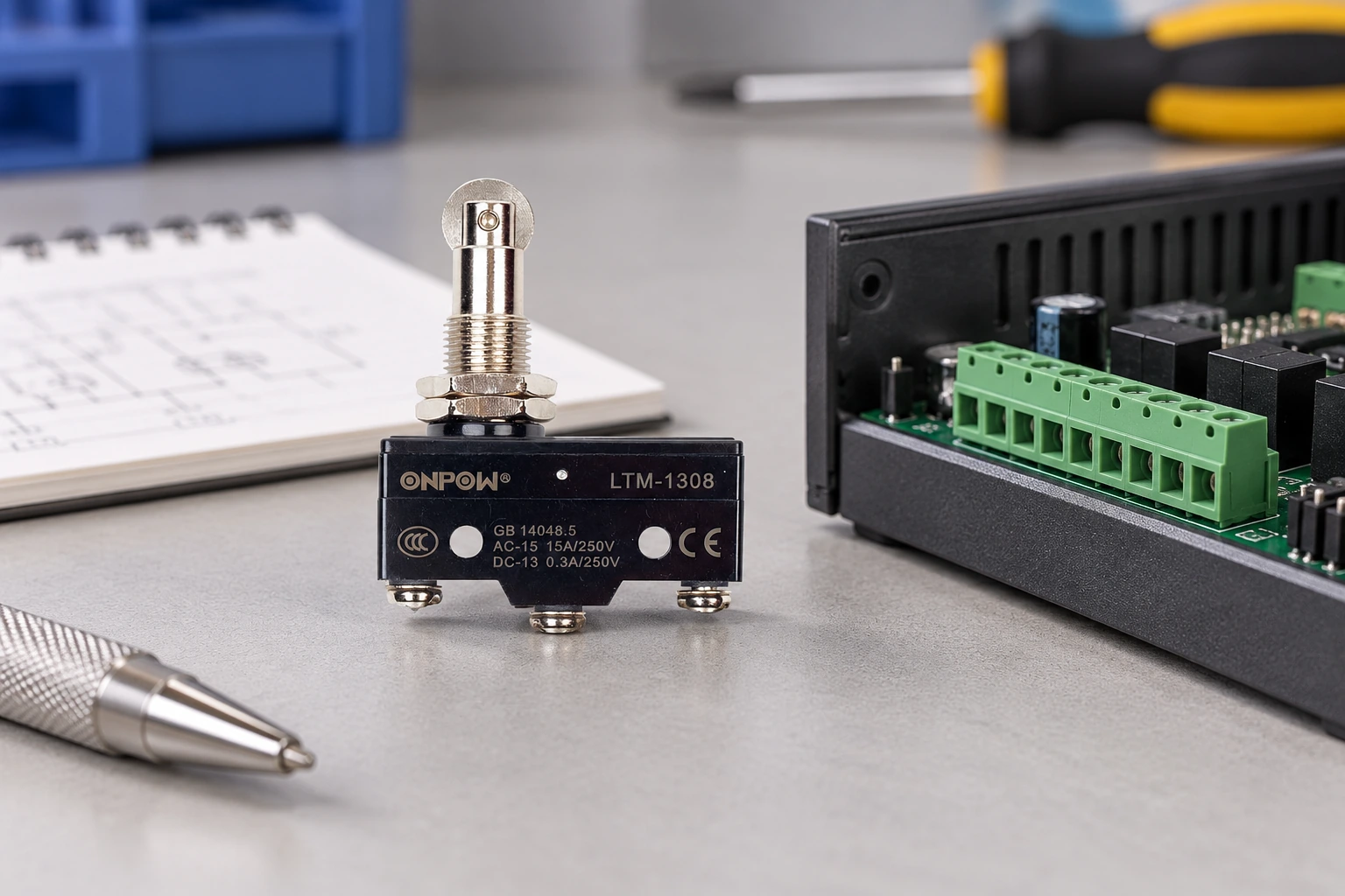
Le ONPOW LTM-1308 product page provides a real mechanical-switch reference. Its photograph and visible higher-load markings do not establish low-level 12V input suitability. Ask ONPOW for the exact variant’s minimum-load information, contact arrangement, and applicable DC data before specifying that use.
Verify the circuit under an approved test plan
Inspection of installed equipment requires qualified personnel and the relevant energy-control procedure. Even where the sensing circuit is 12V, the machine can contain hazardous mains circuits and stored mechanical or fluid energy. For United States workplaces, 29 CFR 1910.147 et 29 CFR 1910.333 provide relevant requirements.
Begin with documented terminal identification and isolated mechanical/contact checks. Do not perform resistance measurements on an energized circuit. Any powered commissioning test must follow the approved equipment procedure and use suitable instruments and access arrangements.
During qualification, verify the expected input state at the allowed supply range and relevant mechanical positions. Include approach and release, the planned input filter, and the real cable route. Record the actual model, receiver, wiring reference, and test conditions so that the result can be repeated after a replacement.
What a complete supplier enquiry should contain
Provide nominal supply voltage, permitted supply range, actual contact current, receiver part number, contact arrangement, switching frequency, target motion, and environment. Explain whether the switch carries an electronic-input signal or a load. If the low-level current is not yet known, identify that as missing information rather than estimating it from another controller.
Ask for confirmation of the electrical interface, low-level contact capability, force and travel data, terminal instructions, and relevant installation limitations. Keep the approved suffix and drawing revision in the maintenance record. A future purchase should not change contact material or actuation behavior unnoticed simply because the body looks identical.
Vidéo éducative
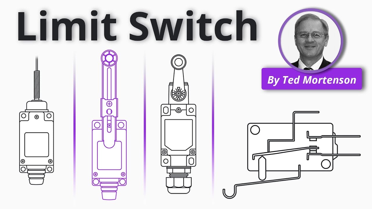
Limit Switch Explained | Working Principles by RealPars. General educational background. Use the selected product drawing and the machine design for the actual circuit and installation. Watch on YouTube.
Foire aux questions
Does a mechanical micro switch need a 12V supply to operate?
A conventional dry contact is mechanically actuated and does not require a sensing supply. The circuit it switches supplies its voltage. Electronic assemblies can have different requirements.
Can an AC-rated micro switch be used at 12V DC?
Do not infer a DC rating from an AC rating. Confirm the declared DC load capability and, for a small input, the minimum switching conditions of the exact model.
Is a higher current rating always better for a PLC input?
No. Low-level contact suitability must be checked separately. A rating for a larger load does not establish performance at a very small input current.
Can I switch a 12V motor directly?
Only a documented rating and circuit design can justify that use. Starting current, stalled current, inductive switching, protection, and life differ from a control-input application.
Why does a 12V input flicker although the switch clicks?
Possible causes include unstable actuation, contact or terminal problems, supply variation, cable noise, inappropriate filtering, or a receiver-interface error. Check each layer against the documented circuit.



