

Panel indicator light brightness has no single value that works for every machine. Choose an indicator that operators can recognize from their normal position under the panel’s brightest expected ambient light, then check it again in dim conditions to avoid glare. Compare the complete product variant and its stated photometric data when available; do not treat a lux reading at the panel as the lamp’s output. Distance, viewing angle, lens, color, reflections, and visual adaptation all affect what people perceive. Finally, assess enclosure sealing and environmental suitability separately: a bright indicator is not automatically weatherproof, and a waterproof rating alone does not make an installation suitable for outdoor use.
Quick answer: select brightness by field visibility, not by “brightest” claims
For a control panel, the useful question is not “Which pilot light is brightest?” It is “Can the intended operator identify the correct signal, at the normal distance and angle, during the least favorable lighting condition?” Start with the real panel, its lens and mounting position, then verify the indicator with the machine in its normal operating states. A setting or component that is easy to see in a dim workshop can be washed out by a nearby window or task light; the same source can feel harsh when the room becomes dark.
The exact electrical and optical variant matters. LED color, lens geometry, supply voltage, internal circuit, and product construction can affect the result. Check the current datasheet or confirm the specific order code with the supplier. Do not infer an indicator’s luminous intensity or brightness from a product photograph or from its nominal voltage.
Brightness, lux, candela, and luminance are not interchangeable
The word “brightness” is often used informally, but light measurements describe different quantities. NIST explains photometry as measurement weighted to the sensitivity of human vision. Illuminance is measured in lux and describes light arriving at a surface; luminous intensity is measured in candela in a direction; luminance is measured in candela per square metre for light emitted or reflected from an apparent surface. These units answer different questions, so a lux-meter reading on the panel is not the indicator’s brightness specification.
For a buyer comparing products, first ask which quantity the manufacturer reports and under what test conditions. If one datasheet gives a luminous-intensity figure and another gives luminous flux, the numbers are not a direct ranking. If no photometric figure is published for the exact variant, avoid inventing a threshold; compare verified product samples on the intended panel instead.
| What you are checking | Common quantity or evidence | What it tells you | What it does not prove |
|---|---|---|---|
| Ambient light falling on the panel | Illuminance, in lux | How much light reaches the panel surface at the measurement point | The indicator’s emitted intensity or whether its color is recognizable at every angle |
| Light emitted in a direction | Luminous intensity, in candela | The directional output under the stated test conditions | The appearance from every viewing angle or distance |
| Apparent emitted or reflected surface | Luminance, in cd/m2 | Light per apparent area in a viewing direction | A universal pass/fail value for every operator or machine |
| Human recognition on the actual machine | A controlled visual check at the operating position | Whether the signal is distinguishable in the tested condition | Compliance with a safety standard or performance in conditions not tested |
Definitions above follow NIST’s photometry resources; the practical field check is an application-specific verification, not a substitute for a required product test or risk assessment. NIST’s photometry overview describes the different measured quantities and their role in evaluating light sources and signals.
The five conditions that change whether a panel indicator is easy to see
1. Ambient light and reflections
Bright daylight through glazing, high-bay fixtures, local task lights, and reflections from polished enclosures can reduce the apparent contrast between an illuminated lens and its surroundings. Look for a reflection landing directly on the lens, not only for the overall room level. Matte panel finishes, better fixture orientation, a small change in panel angle, or moving the indicator within the operator’s normal field of view may solve a visibility problem without selecting a different lamp.
Do not assume that a meter reading alone establishes acceptability. If you use a lux meter, record where and how it was held, because the reading measures incident ambient light at that point. Pair it with a person’s recognition check under documented conditions. Where measured output is a contractual requirement, use a suitably calibrated instrument and a defined method that matches the quantity being specified.
2. Viewing distance and sight line
A small indicator may be obvious at an arm’s length and hard to recognize from a station several metres away. A lens can also become less visible when an operator approaches from the side, looks down from a raised platform, or views the panel through a protective window. Test from the actual standing and seated positions, including the farthest routine operating point and any normal oblique angle.
If a signal must be seen across a large cell or around a machine, a panel-mounted pilot light may be the wrong form factor by itself. Consider whether a larger or remote signal device, a tower light, an HMI message, or another approved indication is required. Do not compensate for poor placement by choosing an unverified lamp or making a safety claim.
3. Lens, bezel, and mounting geometry
The same LED source can look different behind a flat, domed, diffused, tinted, or recessed lens. A deep bezel or nearby guard can restrict the viewing cone. A lens with a narrow apparent face may appear intense head-on but disappear rapidly off-axis; a diffuse lens may be easier to recognize from several directions but can look less concentrated. Compare samples in the actual panel cutout and with the intended bezel, legends, and neighboring controls in place.
Check whether the indicator is flush, raised, hooded, or partly shadowed by an adjacent device. Observe it with the panel door at its final angle if the installation uses a door-mounted panel. The ONPOW AD16 series product page is a starting point for reviewing the site’s panel indicator family; confirm current models, available lens colors, dimensions, terminals, and electrical versions from current product documentation before specifying.
4. Color and visual adaptation
The apparent brightness of two colored sources can differ even when they are measured under a comparable setup, and an observer’s adaptation changes between a bright and a dark setting. A green signal, a red warning, and an amber indication should be tested as separate visual tasks rather than assumed to be equally legible because all three illuminate. Preserve the agreed color meaning and provide labels or symbols so that the operator does not have to rely on color alone.
Le indicator-light color guide discusses common color conventions and why a project must define its own machine-state meanings. Brightness adjustment must not blur that system—for example, by making one color look like an unrelated neighboring state or by washing out a printed legend.
5. Day/night and normal/dim operation
Some machines operate in a production hall by day and are checked in a darkened area at night. A lamp selected only under bright ambient conditions might cause glare after dark; one selected only at night might be missed during daytime. Check each intended operating mode and, if the panel is dimmable, verify the documented dimming range and control method for the exact product. Do not assume an ordinary panel indicator supports dimming or that reducing its supply voltage is an approved way to do so.
A practical brightness verification at the control panel
The following process helps a panel designer or purchaser compare options without pretending that a subjective check replaces a formal photometric test:
- Define the signal and the person who must see it. Record what the indicator means, the operator’s normal position, and the response expected.
- List the lighting conditions that actually occur: bright daylight, overhead lighting, reflections, low-light inspection, and any protective visor or viewing window.
- Confirm the exact indicator variant. Match voltage and circuit type, color, lens, mounting, terminal arrangement, and current product documentation.
- Install the sample in the intended cutout and panel finish. Include adjacent push buttons, legends, guards, and door hardware because they can change reflections and spacing.
- Check recognition from the normal and farthest routine viewing positions. Repeat at the practical side angles and during every relevant ambient-light condition.
- Ask more than one representative operator to identify the signal and state what action it means. A visible lamp can still be confusing if its legend or color assignment is ambiguous.
- Check for glare or distraction in dim conditions, then repeat after the panel has warmed to its normal operating condition if thermal change is relevant to the installation.
- Record the variant, ambient condition, observer position, angle, result, and any instrument used. If an acceptance specification calls for measured photometric data, have the supplier provide the relevant value and measurement conditions.

This comparison is useful for selection and acceptance, but it is not a numerical standard. If a risk assessment, customer specification, or applicable regulation requires a defined visibility level, use that requirement and a competent measurement method. Do not borrow a threshold from emergency-alarm rules and apply it to an ordinary pilot lamp: the device purpose and test conditions are different.
Indoor and outdoor installations: treat brightness and protection separately
“Indoor versus outdoor” describes an installation environment, not a brightness class. An outdoor machine may be shaded or viewed under an enclosure; an indoor machine may face strong sunlight through a window or intense reflected light. Describe the actual light reaching the panel rather than assuming every outdoor location is brighter than every indoor location.
Environmental protection is a separate selection decision. Confirm the specified protection of the complete installed assembly, including the indicator’s front seal, panel surface and cutout, mounting hardware, enclosure, cable entries, and rear terminals. A rating for one component does not automatically certify the assembled cabinet, and a water-resistant front does not establish suitability for UV exposure, temperature cycling, corrosion, cleaning chemicals, impact, or standing water. The selected ingress-protection test and rating must match the applicable project requirement; do not infer it from the word “waterproof” or from a product photo.
For a genuine outdoor application, ask the panel builder or supplier to confirm the exact model’s current environmental limits and the installation details that preserve them. Then repeat the visibility test under the real ambient light, with reflections, weather shields, covers, or glazing installed. Keep the two records separate: one for visual recognition and one for environmental qualification.
Erreurs courantes de sélection
Choosing the highest advertised number
“Brighter” does not automatically mean easier or safer to read. The stated quantity, viewing direction, lens, ambient light, and operator position matter. Compare only like-for-like specifications and confirm their test conditions.
Measuring only panel illuminance
A lux meter can describe light arriving at the panel. It does not directly measure the indicator’s output. Use it to document ambient conditions, then perform a recognition check or a formal measurement appropriate to the required quantity.
Checking from one position
The panel may look clear from the person installing it and be unreadable to an operator standing to the side. Test routine sight lines and distances, not just a straight-on close-up.
Equating “waterproof” with outdoor-ready
Ingress protection is only one environmental consideration. Seal installation, enclosure details, UV, temperature, corrosion, and cable entry all matter. Brightness does not establish any of these conditions.
Assuming higher voltage means a brighter indicator
Voltage identifies an electrical supply variant; it is not a universal brightness scale. Compare the exact product’s verified optical data and field result, not nominal voltage alone. For related selection context, see 12 V versus 24 V LED indicator lights et metal versus plastic indicator-light housings.

Questions to send with an indicator-light RFQ
Include these details when asking a supplier to recommend a panel indicator:
- exact machine state, required operator action, and agreed signal color;
- normal and farthest viewing distance, expected sight angle, and viewing window or visor;
- actual ambient-light conditions, including daylight, task lights, reflections, and dim operation;
- panel cutout, thickness, bezel, lens style, legend, front protection, and rear clearance;
- AC or DC supply, nominal voltage, circuit details, and any required dimming behavior;
- the optical quantity requested, its unit, and the test condition if a numeric comparison is required;
- temperature, vibration, cleaning, moisture, chemicals, UV, corrosion, and other environmental conditions;
- whether the acceptance check is a visual recognition test, a measured photometric requirement, or both.
Le ONPOW signal-lamp range et indicator-light selection guide can help narrow the product family. Ask ONPOW to confirm the exact available variant and current specifications; the article and product images are not substitutes for an approved datasheet.
Educational video: what photometric measurements describe
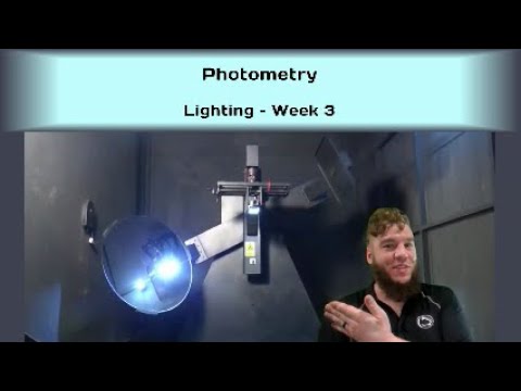
The following educational video, “Photometry,” by J. Mundinger of Penn State’s Lighting Lab, introduces photometric quantities such as luminance and illuminance. Penn State’s Lighting Lab lists J. Mundinger as a research technologist. The video provides background for understanding why ambient lux and a lamp’s directional output are different measurements; it does not specify ONPOW product performance or a required acceptance threshold.
Foire aux questions
How bright should a panel indicator light be?
There is no single value that fits every panel. Verify that the intended operator can recognize the correct signal at the normal and farthest routine viewing positions under the brightest expected ambient condition, then check for glare in dim conditions. Use a defined photometric requirement if the project or regulation calls for one.
Does a lux meter measure an indicator light’s brightness?
Not when it is used to measure illuminance at the panel. Lux describes light arriving at a surface. A measurement of the lamp’s emitted output requires an instrument and setup suitable for the specified photometric quantity, such as directional luminous intensity or luminance.
Is a brighter LED indicator always easier to see outdoors?
No. Direct sun or reflections may make a signal harder to distinguish, but lens direction, glare, angle, distance, color, and visual adaptation also matter. Test the actual device and installation under the site’s real lighting conditions.
Does a waterproof indicator automatically suit outdoor use?
No. Verify the exact protection rating and installation, then assess UV, temperature, corrosion, chemicals, impact, cable entries, and the enclosure as applicable. Visibility and environmental suitability are separate checks.
Should I choose a higher-voltage model for more brightness?
No. Voltage is an electrical specification, not a reliable brightness ranking. Compare the exact variant’s stated optical information under comparable conditions and confirm visibility on the intended panel.
Final checklist
Choose panel indicator light brightness from a real viewing task: defined signal, identified operator, actual panel, expected sight line, and the worst practical ambient-light condition. Compare photometric specifications only when they describe the same quantity and test setup. Check color, lens, glare, labels, and visibility in both bright and dim use. Keep environmental qualification separate from brightness, especially for an outdoor indicator light. When product specifications are incomplete, request the current datasheet or sample and document the actual acceptance check rather than assuming a number.
Sources: NIST Photometry; NIST SI definition of the candela; Penn State Lighting Lab; IEC 60073:2002 coding principles for indicators and actuators.



