

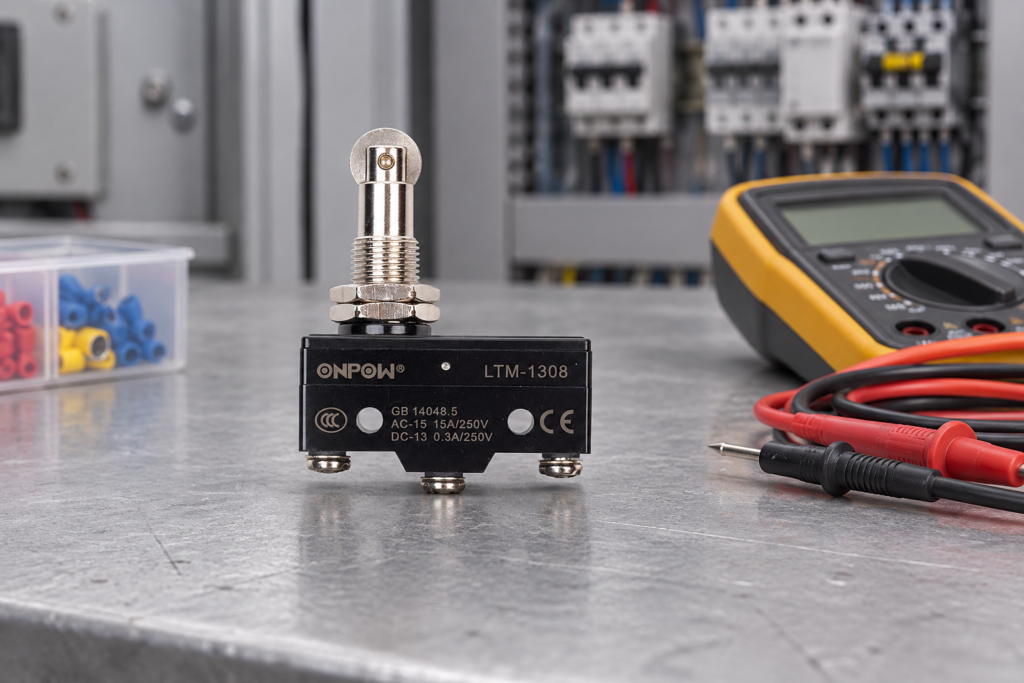
A micro switch wiring diagram shows how the common terminal changes connection between normally closed and normally open contacts as the actuator moves. For a conventional SPDT switch, COM connects to NC at rest and to NO after operation. That describes contact logic, not a universal terminal layout. Check the exact model drawing, identify the reference actuator position, and match the contact rating to the circuit before connecting anything. An isolated continuity test can confirm the two states. It cannot establish the switch’s voltage rating, approve a machine safety function, or replace the equipment wiring diagram.
Read the contact diagram before the terminal position
COM is the shared moving-contact connection. NO and NC describe the contact paths relative to the manufacturer’s defined normal position, commonly an unoperated actuator. They do not describe whether the machine is normally running. A switch installed under a cam can remain mechanically operated throughout normal production, so the controller’s normal signal may come from the contact marked NO.
Do not assume the middle screw is COM, that the terminal nearest the plunger is NC, or that another supplier’s numbering matches. Terminal orientation can change with actuator, mounting, and termination options. Photograph the label, record the full part number and suffix, and obtain the matching contact drawing. If the drawing is missing or illegible, stop the substitution until the circuit is identified.
For a wider explanation of the snap mechanism, read how a micro switch works. This article concentrates on identifying and documenting the electrical connections rather than choosing an actuator.
| Actuator condition for a conventional SPDT example | COM–NC path | COM–NO path | What to record |
|---|---|---|---|
| At the defined normal position | Fermé | Ouvrir | Reference position and terminal identities |
| Beyond the specified operating point | Ouvrir | Fermé | Travel direction and operated signal |
| During release before the reset point | Depends on mechanical history | Depends on mechanical history | Release position and hysteresis |
| Wire removed or damaged | Circuit-dependent loss of signal | Circuit-dependent loss of signal | Controller response and diagnostic coverage |
This table is a contact-state example, not an ONPOW terminal map or a claim about every changeover product. Use the exact drawing to confirm whether the device provides SPDT contacts and how its transfer is specified.
Separate the switch contact from the controller input
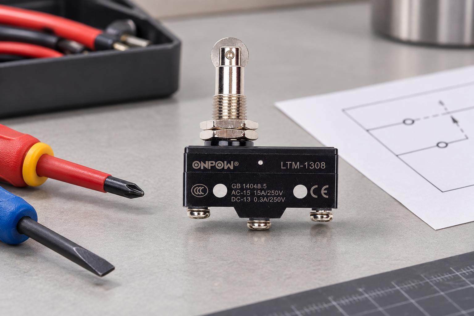
A dry contact does not create a voltage. It completes or interrupts a circuit supplied elsewhere. In a control input circuit, the switch may connect a supply to an input, connect an input to a reference, or operate through an interface module. Those arrangements are electrically different even when the same COM–NO contact pair is used.
Identify the input module’s supply, reference, input threshold, permitted leakage, current requirement, and wiring convention. A PLC drawing that uses one common arrangement is not proof that another module uses it. Sourcing and sinking input circuits need the correct relationship between supply and return. Keep the controller manual with the switch drawing so that the field wiring can be traced end to end.
As a conceptual example, a compatible input circuit can read a contact path as an operated signal. The input may then be inverted or interpreted by software. A lit input indicator proves only that this input has reached its switching threshold; it does not prove that the actuator is in a mechanically safe position. Verify the displayed state against physical position and the equipment’s documented sequence.
Decide what the normal and fault states must mean
Choose NO or NC from the required behavior of the complete circuit. For a simple indication, NO may produce a signal when a part arrives. NC may provide a continuous signal that disappears when a mechanism reaches a limit. Either choice needs a defined response to an open cable, a short circuit, a stuck actuator, and a failed input.
An NC loop can reveal some open-circuit failures, but it does not automatically detect every fault. A short across the switch may keep the circuit appearing healthy, and a welded contact may prevent the intended state change. Do not describe a conventional NC switch as inherently fail-safe. A safety-related function needs the specified protective device, circuit architecture, diagnostics, and validation for the machine.
For the practical difference between a component and a packaged position sensor, see micro switch versus limit switch. For a housed limit-switch circuit, the separate NO/NC limit-switch wiring guide addresses that installation context.
Confirm the load category, not only the printed current
A resistive current rating cannot be transferred automatically to a relay coil, solenoid, motor, lamp, or very small electronic input. These circuits place different stresses on the contacts. An inductive load creates an opening transient; an electronic input may require a contact material and minimum switching condition suitable for a small signal.
Check the rated operational voltage and current for the specified load category, AC or DC operation, switching frequency, ambient conditions, and expected electrical life. A thermal current marking and a contact switching rating answer different questions. Keep them separate in the purchasing specification. The IEC 60947-5-1 publication information identifies the standard’s scope for electromechanical control circuit devices; its existence does not certify an individual model or provide that model’s ratings.
If the input is a low-current DC circuit, request the manufacturer’s low-level switching information. If a coil is being switched, confirm the coil load, interface, and suppression design. Do not add a flyback diode to an AC circuit by analogy with a DC diagram. If the contact cannot support the actual load, use a correctly designed interface rather than increasing the fuse or relying on an oversized printed rating.
Verify contacts with the circuit isolated
Only qualified personnel should test or modify installed electrical equipment. Follow the machine’s energy-control procedure, including stored mechanical, pneumatic, hydraulic, and electrical energy. For United States workplaces, 29 CFR 1910.147 addresses hazardous-energy control, while 29 CFR 1910.333 covers relevant electrical work practices. Apply the rules appropriate to the workplace and equipment.
A resistance or continuity instrument is used on a deenergized, suitably isolated circuit. Parallel paths through other devices can give misleading readings. Identify the terminals from the drawing, disconnect or isolate as required by the approved procedure, and compare the meter result in the defined unoperated and operated states. Do not use a continuity beep as proof that a contact can interrupt its rated load.
Move the actuator through its intended travel without forcing it past the permissible position. Record the state change and release behavior. A click without the expected electrical transition calls for investigation; an intermittent reading can arise from contact damage, loose connections, an incorrect meter range, or unstable actuator motion. Resolve the cause before putting the device back into service.
Wire and document the actual installation
Use the correct conductor size, terminal type, tightening method, and strain relief from the selected product’s instructions. Protect the conductors from moving parts and sharp edges. A wire that is electrically correct but pulls on a terminal during every machine cycle is a maintenance fault waiting to develop.
Label the conductors with the equipment’s wire numbers and record the switch terminal designation beside each one. Do not use wire color as the only identity. Include a clear view of the installed actuator, its normal position, the terminal cover, cable routing, and the bracket. The diagram should show which path is used and what the controller should report in each operating state.
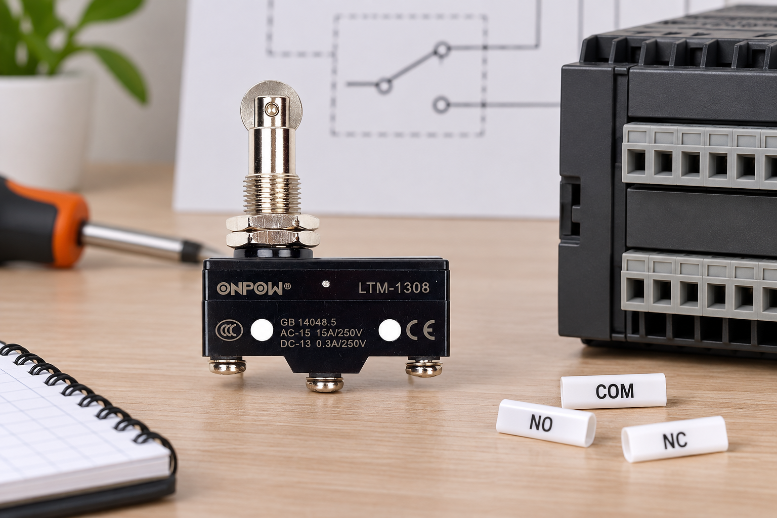
Le ONPOW LTM-1308 product page provides a real mechanical-switch example for discussing installation. Its photographs illustrate the body and actuator; they are not substitutes for a model-specific contact drawing. Ask ONPOW for the exact variant’s contact arrangement, switching data, terminal instructions, and dimensional information before specifying it for the application.
Commission the signal together with the mechanism
After the approved restoration of energy, test through the documented commissioning process. Confirm the physical position, the contact state, the controller input, and the resulting action. A correctly changing input can still be assigned to the wrong program address. Compare the live indication with the wiring schedule and control narrative.
Check approach and release in both directions that the mechanism can actually travel. Confirm the actuator resets when the target leaves, and that normal overtravel remains within the manufacturer’s limit. If vibration makes the input chatter, investigate the mechanical dwell and control timing rather than hiding a poor mounting arrangement behind excessive filtering.
Record the result in a simple state matrix: target absent, target arriving, target present, target leaving, and any approved diagnostic test. Include the expected machine response and the person who completed the verification. Changes to the bracket, actuator, contact suffix, or controller input require review because they can alter the meaning of the signal even when the wiring colors remain unchanged.
Purchasing checklist for a wiring-compatible replacement
Provide the full existing part number, contact drawing, circuit voltage, load type, input-module reference, actuator type, mounting dimensions, and operating environment. Include the present conductor termination and the required normal and operated states. State whether the component is part of ordinary process feedback or a specified protective function.
Ask the supplier to confirm terminal identity and electrical suitability in writing. A replacement that physically fits but swaps the contact meaning can reverse an indication. A different actuator can also change when the contact transfers. For mechanical selection alongside wiring, use the industrial micro switch selection checklist and keep the final electrical and mechanical drawings together.
Vidéo éducative
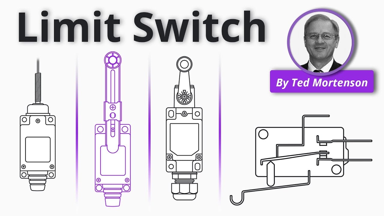
Limit Switch Explained | Working Principles by RealPars. General educational background. Use the selected product drawing and the machine design for the actual circuit and installation. Watch on YouTube.
Foire aux questions
Is COM always the center terminal?
No. Terminal position and numbering depend on the exact product. Identify COM from the matching contact drawing and verify the isolated contact states when appropriate.
Can I connect the same supply to NO and NC?
Do not improvise a connection from the terminal names. NO and NC are alternate paths of a conventional changeover contact. The machine drawing and controller interface determine which paths are used and whether they share a permitted circuit.
Does a micro switch need its own power supply?
A conventional mechanical dry contact does not require a separate sensing supply. The circuit it switches needs an appropriate supply. Electronic switches and integrated assemblies may have different requirements.
Is an NC micro switch a safety switch?
NC describes a contact state. It does not establish a safety rating, direct-opening behavior, diagnostic coverage, or approval for a protective function. Select and validate the complete safety circuit separately.
Why does the meter show continuity on the wrong pair?
Possible causes include mistaken terminal identification, an actuator held operated by the machine, parallel circuit paths, or a damaged contact. Isolate and inspect the device under the approved procedure, then compare it with the exact drawing.
Customization
ONPOW undertakes a variety of custom needs for push-button development. Confirm whether packaging, marking or documentation OEM/ODM applies to Micro Switch Wiring Diagram: COM, NO and NC Terminals in the quotation.
Minimum order quantity, lead time and trade terms are not published here; confirm them with sales at sales@onpow.com.



