

A capacitive touch switch can sometimes detect a finger through glass or plastic, but the result depends on the sensor design and the complete material stack. Overlay thickness, dielectric properties, air gaps, electrode size, grounding, sensor tuning, and the user all affect the available signal. “Capacitive” does not mean that every switch works through every cover. Texas Instruments’ TIDA-00343 reference design, for example, reports detection through a specific 10 mm glass window with a defined sensor/controller design; that is evidence for that design, not a specification for unrelated products.
This article explains how to evaluate touch through glass and plastic without assuming that an ONPOW metal touch switch supports a cover or a particular thickness. Treat the values in any vendor reference design as an example, and validate the exact sensor, overlay, enclosure, and environment you plan to use.
Why a capacitive sensor can respond through a cover
A capacitive sensing electrode establishes an electric field around its active area. A nearby finger changes the field and therefore the measured capacitance. A nonconductive cover such as glass, acrylic, or another plastic can sit between the electrode and the finger while still allowing a measurable change. The controller must distinguish that change from the sensor’s baseline and from noise.
The cover is part of the sensing system. A thicker or lower-permittivity material can reduce the change observed at the electrode. An air gap between the electrode and cover can also reduce coupling. A larger electrode may improve coupling in some designs but can increase parasitic capacitance, cross-talk, or sensitivity to nearby objects. The best geometry depends on the controller and the desired touch area, so there is no universal maximum thickness to quote for “capacitive touch.”
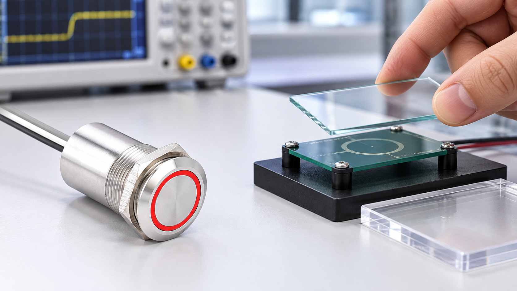
TI’s TIDA-00343 is a useful documented example: its design describes a variable air gap and detection through 10 mm glass under its specified implementation. Do not transfer that number to a different controller, panel, or switch. TI’s CapTIvate design guidance and Microchip’s capacitive touch design material likewise emphasize electrode layout, materials, spacing, and environmental effects as design variables.
Glass, acrylic, and other plastics are not interchangeable
| Overlay variable | What it can change | Practical evaluation |
|---|---|---|
| Matériau | Dielectric response and losses differ by material and formulation | Test the exact glass or polymer grade, not only a generic sample label |
| Thickness | More material between finger and electrode can reduce the detectable change | Test minimum, nominal, and maximum production thicknesses |
| Air gap | Adds separation between the electrode and overlay | Include gasket, adhesive, spacer, and assembly tolerance in the sample |
| Surface finish | Coating, printing, texture, or tint may change the sensor interface | Include ink, screen print, paint, and protective films in the final sample |
| Electrode size | Affects field shape and coupling area | Use the actual sensor geometry and intended touch target |
| Nearby conductors | Can distort or shield the field | Include grounded frames, screws, displays, and cable shields in the test |
| User and glove | Changes coupling and effective distance | Test representative users, bare fingers, and each required glove type |
The table is qualitative. It does not assign material constants or guarantee a sensing distance. A published material value is useful only when it matches the exact formulation, frequency, and measurement conditions of the design.
Keep overlay testing separate from product selection
An industrial touch product may have a flat metal face that itself forms the operator surface. That is physically different from a sensor mounted behind a glass or plastic window. Do not infer through-cover capability from a round metal front, a product category name, or a photograph. ONPOW’s TS19A product et TS22D product pages should be reviewed for the actual construction and ordering information. If the required interface needs sensing through an overlay, obtain written confirmation for the exact model and configuration before design release.
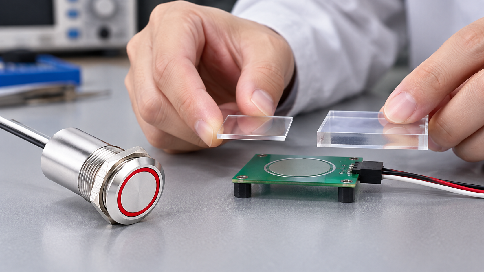
For a custom sensor, keep the sensing electrode, controller board, and overlay coupon distinct during the early test. Change one variable at a time: material, thickness, gap, electrode size, grounded frame, or user condition. Record the sensor configuration and firmware or controller settings so that a later test can be reproduced. After basic bench testing, move to the actual enclosure and nearby metalwork; a coupon on a laboratory table is not an assembled machine. For broader interface selection, see ONPOW’s metal-panel capacitive touch circuit guide et cURL Too many subrequests by single Worker invocation. To configure this limit, refer to https://developers.cloudflare.com/workers/wrangler/configuration/#limits.
cURL Too many subrequests by single Worker invocation. To configure this limit, refer to https://developers.cloudflare.com/workers/wrangler/configuration/#limits.
A repeatable overlay validation process
cURL Too many subrequests by single Worker invocation. To configure this limit, refer to https://developers.cloudflare.com/workers/wrangler/configuration/#limits.
cURL Too many subrequests by single Worker invocation. To configure this limit, refer to https://developers.cloudflare.com/workers/wrangler/configuration/#limits.
cURL Too many subrequests by single Worker invocation. To configure this limit, refer to https://developers.cloudflare.com/workers/wrangler/configuration/#limits.
cURL Too many subrequests by single Worker invocation. To configure this limit, refer to https://developers.cloudflare.com/workers/wrangler/configuration/#limits.
Information to confirm before specifying an overlay
cURL Too many subrequests by single Worker invocation. To configure this limit, refer to https://developers.cloudflare.com/workers/wrangler/configuration/#limits.
If the supplier cannot confirm the stack-up, use a non-production evaluation fixture and agree acceptance criteria before testing. Record successful touches and false activations, then repeat the test after the enclosure and electrical installation are complete. Do not convert a one-off demonstration into an environmental or safety claim.
Common mistakes when specifying touch through glass or plastic
The most common error is copying a maximum thickness from another vendor’s reference design. That result belongs to the specific controller, electrode, glass, air gap, firmware, and test procedure used in that project. It should not be presented as an industry-wide limit or as ONPOW product data.
Another error is testing only clear, uncoated glass and then releasing a tinted or printed production panel. Paint, conductive coatings, metal trim, adhesives, and decorative layers can change coupling. Likewise, the sample may be thin at its center but thicker at its edge, or production tolerances may enlarge an air gap.
Designers also sometimes treat a successful touch as proof that the interface is suitable for a machine command. Touch detection and the machine’s response are separate. The application still needs appropriate logic, feedback, fault behavior, access control, and safety validation. See ONPOW’s capacitive and piezoelectric switch comparison et guide des interrupteurs tactiles versus boutons-poussoirs for the broader interface decision.
Foire aux questions
Le toucher capacitif peut-il fonctionner à travers le verre ?
Yes, in a design engineered and validated for the selected sensor and glass assembly. Performance depends on thickness, spacing, electrode geometry, controller settings, and the real enclosure; it is not guaranteed for every touch switch.
Le toucher capacitif peut-il fonctionner à travers du plastique ?
Cela peut, en fonction de la formulation du plastique, de l'épaisseur, du revêtement, de l'écart, de la conception du capteur et du contrôleur. Testez le matériau de production exact et la pile plutôt que de vous fier au mot générique “ plastique ”.”
Un exemple de 10 mm signifie-t-il que n'importe quel capteur fonctionne à travers 10 mm de verre ?
Non. TI indique que la performance concerne son design de référence TIDA-00343 et sa configuration définie. C'est un exemple, et non une limite universelle ou une spécification ONPOW.
Un commutateur en métal ONPOW touche-t-il un interrupteur derrière une couverture en verre?
Ne pas supposer cela. Confirmer la construction exacte du produit et l'installation prévue avec sa documentation actuelle ou ONPOW, puis tester le panneau assemblé si une superposition est requise.
Que doit être testé avant la production?
Test the actual overlay material, thickness tolerance, finish, air gap, frame, grounding, sensor settings, bare-finger and required-glove use, nearby interference, startup, and final enclosure configuration.
Vidéo éducative
This Texas Instruments reference-design video demonstrates touch input through a defined glass window. Its performance belongs to that TI design and does not establish a thickness or through-cover rating for ONPOW products.

Watch the Texas Instruments touch-through-glass reference design.
Références
- Texas Instruments TIDA-00343 : Conception de référence pour le toucher à faible consommation à travers le verre
- Texas Instruments CapTIvate capacitive-sensing design guide
- Microchip AN2934 : Guide de conception du capteur tactile capacitif (PDF)
Produits et guides ONPOW associés
Revoir le Interrupteur tactile TS19A et Interrupteur tactile TS22D pages for product-specific construction. For selection context, read Touch Switch vs Push Button and ONPOW’s capacitive and piezoelectric switch comparison.



