

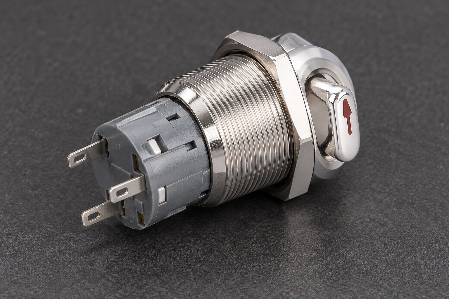
An illuminated selector switch combines a rotary selection action with a light, but its visible position and its illuminated message are different pieces of information. The lever indicates a mechanical selection; the lamp shows only the condition assigned by its circuit. For an industrial panel, specify the position-by-position contact table, maintained or spring-return action, lamp supply and the exact meaning of illumination. Then test the arrangement against the controller sequence. A lit selector does not automatically confirm that a requested mode has been accepted, and an arrow on the lever does not establish the rear terminal connections.
Begin with the mode-selection task
A selector can choose between modes, sources or control requests. Identify the actual task before choosing a head and lamp color. An operator selecting manual operation needs a different message from someone checking whether a control supply is available.
Write the permitted selections in a state table. Include what the controller should do when a selection is requested and when another condition prevents acceptance. For a machine that supports several modes, do not assume that turning the lever immediately changes every part of the equipment’s operating state.
The ONPOW key and selector switch range provides the relevant product category. The LAS1-AGQ22-11X/21/S product page lists lamp and contact options for the referenced selector family. Confirm the exact ordered combination and its diagram; the family listing does not make every option interchangeable.
Position feedback starts with a contact table
Record the state of each contact in each mechanical position. Include the defined reference position and any automatic return action. That table is the basis for the command inputs and remains necessary even when the illuminated head appears easy to understand.
A two-position operator and a three-position operator can have different switching sequences. Contact blocks and their assembly can also change the available functions. Do not translate the lever’s visible angle into assumed terminal states.
For a multi-mode circuit, check the intended transitions between positions. A intermediate movement can have a documented contact sequence that matters to the controller. Ask for the actual diagram and the control-system requirements instead of assuming that every selector uses the same transition behavior.
The two-position selector guide and three-position HOA guide develop those contact-logic topics. This article focuses on adding a useful light to the selection task, rather than repeating their wiring examples.
Choose the lamp message separately
There are several legitimate lamp messages. The light can help locate the operator, indicate supply availability, follow a selection request or communicate a controller-confirmed condition. They should not all be described as “position feedback.”
If the light follows the selected contact, it can indicate a request. If a permissive rejects that request, the lamp may still remain on unless the circuit was designed otherwise. A label that says “AUTO ACTIVE” would then be inaccurate if the circuit establishes only “AUTO REQUESTED.”
A controller output can support a different indication, but document what that output proves. Software acceptance, a retained command and actual plant behavior are not identical. The complete design must determine which condition the operator needs to see and what happens when the evidence is unavailable.
A lamp-message decision table
Use this table to approve the display meaning before choosing conductors or labels. It supplies design questions without prescribing undocumented terminal connections.
| Intended light message | Design question | Acceptance condition |
|---|---|---|
| Operator location | Is illumination only for finding the control? | Labels do not imply machine operation |
| Control supply available | Which supply does the lamp monitor? | The display identifies that limited message clearly |
| Mode requested | Does the light follow the selected request contact? | Rejected requests are not presented as accepted modes |
| Mode accepted | What controller condition establishes acceptance? | The display follows the documented acceptance condition |
| Plant operating | What evidence establishes actual operation? | The light does not rely solely on a request or selected position |
| Fault or unavailable feedback | What should happen if the indication cannot be trusted? | The operator receives appropriate state information through the approved design |
Review the table with operators as well as the controls designer. The most elegant circuit is not useful if workers consistently interpret its message differently from the design record.
Separate lamp supply from contact duty
The referenced ONPOW product family lists lamp options, but the correct version depends on the intended supply. Confirm voltage, AC/DC requirements, any polarity restrictions and the exact connection instructions. Never use appearance alone to identify the lamp terminals.
The contacts require their own duty assessment. A lamp voltage does not establish a contact’s ability to switch a load at that voltage. Specify the actual input or load, relevant ratings and operating sequence independently of the illumination option.
If an electronic output controls the lamp, check compatibility with that output’s documented behavior. Diagnostic pulses, leakage or other output characteristics may affect the visible indication. The solution belongs in the verified circuit design rather than in an assumed universal LED connection.
For a keyed alternative, the illuminated key switch guide adds access and key removal considerations. A rotary selector without a key and a keyed operator can support related selection tasks, but their access behavior and procurement requirements differ.
Keep the lever marking and panel label consistent
A lever arrow tells the operator where the selector points. A panel label identifies the intended positions. A lamp adds another message. Check the three together so that a person can interpret the selection without guessing which indication has priority.
Do not invent universal meanings for a red or green lamp without the applicable equipment conventions. Review the machine’s procedures, neighboring controls and alarm hierarchy. If the selector sits among several indicators, its local light should not obscure a more important state or create an ambiguous duplicate.
The HSE control-room guidance identifies controls, displays, lighting and the wider work setting as connected design concerns. For a local machine panel, that supports evaluating the real viewing and operating task rather than judging the selector on a bright product photograph alone.

Viewing angle and operating conditions
Inspect the indication from where workers normally stand. A lever can partially obscure a light, and a visible ring can appear different from an oblique angle. The exact head design, label placement and ambient illumination all affect interpretation.
Check the panel during the relevant operating conditions. Strong ambient light can make a small light difficult to distinguish; dim conditions can make a bright local indicator distracting. Ask for appropriate visibility evidence or an application sample where the message is important.
Gloves, reach and operating space also matter. An illuminated head should not be selected at the expense of a clear grip or sufficient clearance around the lever. Review neighboring controls so that an operator does not unintentionally disturb another selection while turning the device.
Off does not always mean electrically isolated
A selector marked “OFF” can represent a normal control state while other energy remains available. Likewise, a dark lamp can result from supply loss or lamp failure without establishing that the machine is isolated. Keep that distinction clear in the operating and maintenance procedures.
The US requirements in 29 CFR 1910.147 provide hazardous-energy context. A normal control device is not automatically an energy-isolating device. Do not describe turning the selector or observing its lamp as a complete servicing safeguard.
Where a selector participates in a safety-related function, involve the responsible designer and appropriate assessment. Illumination does not establish diagnostic coverage, safety integrity or suitability for a protective function. The necessary system evidence must be obtained separately.
Commission both the command and the display
Acceptance should compare the delivered part with the approved position table, contact drawing and lamp specification. Under the responsible procedure, verify that every selection produces the intended electrical request and that the return action, if present, matches the brief.
Test the light in each defined condition. Include a request rejected by the controller where that condition is relevant. Check loss and restoration of power against the approved sequence. A maintained lever can remain selected while the system’s response after restoration depends on its logic.
Record the final panel label and display message. If a discrepancy is found, resolve its cause rather than making an informal assumption about what the light now means. The accepted drawing should agree with what operators are told and what maintenance staff later inspect.
Replacement and inquiry checklist
A matching cutout is only the start of a replacement comparison. Confirm position count, contact sequence, return action, lamp version, head marking and mounting requirements. A replacement can fit mechanically while communicating or requesting a different state.
Send ONPOW the marked position diagram, contact table, lamp supply, intended light message and photographs of the panel. Include the relevant input or load information. Ask for confirmation of the exact available configuration rather than assuming the product-family options describe one universal model.
Retain the final drawing and commissioning results. The next buyer should be able to identify why the chosen lamp and contact assembly were specified, without reconstructing the design from a photograph of the front panel.
Further learning: wiring diagrams and mode logic
The RealPars lesson explains how basic wiring relates to PLC programming. It provides background for separating a physical selector contact from the controller’s decision. It does not establish the terminal layout or safety properties of the illustrated ONPOW selector.
Frequently asked questions
Does a lit selector prove that a mode is active?
Only if the documented indication circuit establishes that condition. The lamp might instead follow a request, identify the control or show supply availability. Define and test its message.
Can the arrow replace a contact table?
No. The arrow describes visible operator position. Use the exact contact diagram to establish terminal states and the controller’s required input sequence.
Is the lamp voltage the contact rating?
No. Lamp supply and contact duty are separate specifications. Confirm both for the exact ordered version and actual circuit.
Can a dark lamp prove the equipment is isolated?
No. Lamp failure or supply loss can produce darkness without establishing energy isolation. Use the authorized equipment procedure and applicable requirements for servicing.
What should a quotation include?
Provide the position diagram, contact table, return action, lamp supply, intended message, electrical duty and mounting details. Ask the supplier to confirm the exact available configuration.



