

A double pole double throw toggle switch contains two electrically separate changeover poles operated by one lever. Six terminals are common, but their physical order is not universal. Identify both common terminals and their two throws from the exact drawing or by an isolated continuity test before connecting a control circuit. This guide explains a safe identification and verification process for engineers, panel builders, maintenance teams and buyers. It does not replace the current datasheet, machine risk assessment or locally applicable electrical requirements. The method keeps each decision traceable during purchasing, assembly, commissioning and later service.
Gyors döntés
A funkcióval kezdjen, ne a lábszámmal. Írja össze a szükséges stabil és pillanatnyi állapotokat, azonosítson minden érintkező- és lámpakört, majd illessze a dokumentált névleges értéket a tényleges terheléshez. Az azonosítás alatt tartsa leválasztva a tápfeszültséget. Beszerelés után tesztelje mind az elektromos állapotot, mind a gép reakcióját. Ha a alkalmazás veszélyes mozgást vezérel, az általános célú kapcsoló teljes körű biztonsági funkcióként való kezelése helyett alkalmazza az előírt biztonsági architektúrát.
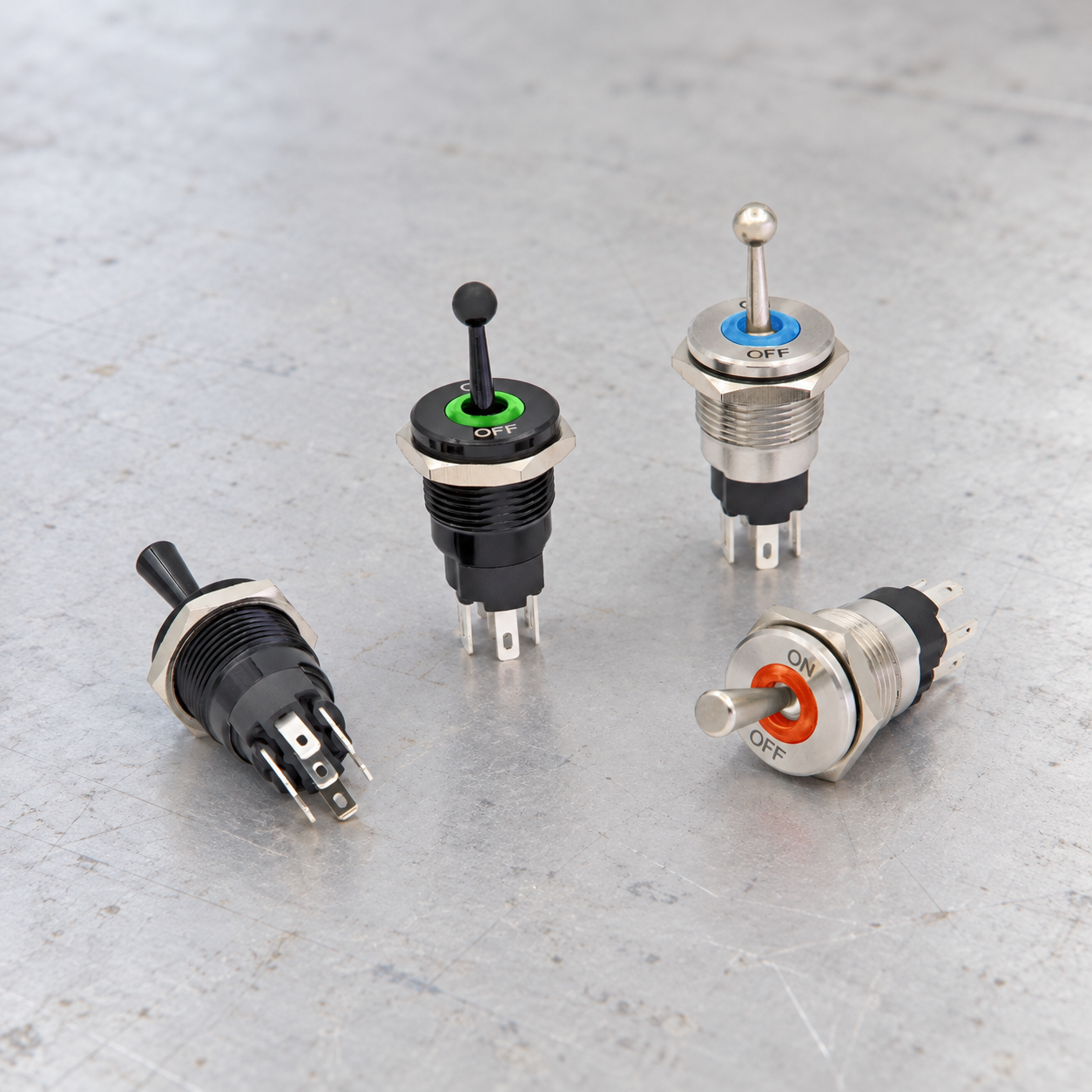
Kiválasztási és huzalozási szempontok
| Döntés | Mit kell ellenőrizni | Mérnöki indok |
|---|---|---|
| Two poles | Confirm that the two contact sections are electrically isolated | DPDT describes contact logic, not a permission to combine unrelated voltage systems. |
| Common terminals | Locate one common for each pole | The moving contact transfers each common between two throws. |
| Lever positions | Record the connection matrix in every position | ON-ON, ON-OFF-ON and momentary variants behave differently. |
| Terminal layout | Use the model drawing or continuity measurements | A six-lug pattern can be rotated or internally arranged differently. |
| Reversing logic | Use cross-connections only in an engineered low-voltage reversing circuit | A wiring pattern must include safe stop, protection and prevention of simultaneous commands. |
| Load category | Check AC or DC, resistive or inductive duty and inrush | A printed current alone does not define every permitted load. |
| Circuit separation | Keep poles within insulation and system design limits | Separate poles are not automatically approved for unrelated hazardous potentials. |
| Ellenőrzés | Test continuity before energizing and function after installation | The complete machine response matters more than the lever label. |
Ez a táblázat szándékosan minőségi jellegű. A numerikus besorolásoknak, a nyomatéknak, a vezeték méretének, a szigetelési távolságnak, az élettartamnak és a környezeti határértékeknek a pontos eszköz jóváhagyott dokumentumaiból és a teljes berendezés tervezéséből kell származniuk. A hasonló megjelenésű kapcsolók eltérő belső csatlakozásokat használhatnak.
Értse meg a kapcsolási logikát a huzalozás előtt
A pólus azt írja le, hogy mennyi független közös érintkezési út működik együtt. Az áramkörök száma (dobás) azt írja le, hogy az egyes közös érintkezők hány rögzített érintkezőt tudnak kiválasztani. Ezek a kifejezések nem határozzák meg a karállások számát, hogy egy állás rögzített vagy pillanatnyi-e, hogy az érintkezők átlapolódnak-e az átkapcsolás során, vagy hogy a visszajelző lámpa hogyan van csatlakoztatva. Ezekhez a részletekhez állásonkénti érintkezési táblázatra van szükség.
Rajzoljon egy mátrixot, amelynek a tetején a csatlakozók, az oldalán pedig a működtetőelem-pozíciók szerepelnek. Csak az aktuális rajz vagy szigetelt mérések által támogatott csatlakozásokat jelölje meg. Adjon meg egyértelmű nézeti irányt, például “hátsó csatlakozó nézet felfelé álló működtetőelemmel”. Ez az egyszerű nyilvántartás megakadályozza, hogy az összeszerelés vagy a későbbi szervizelés során összetévesszék a tükrözött rajzokat, a elforgatott alkatrészeket és a kábelköteg-üregszámokat.
Two poles
Mit kell ellenőrizni: Confirm that the two contact sections are electrically isolated. DPDT describes contact logic, not a permission to combine unrelated voltage systems. The engineering record should name the exact order code, drawing revision, supply, load and operating state used for the decision. Check the component in its installed orientation because panel thickness, wire routing, adjacent hardware and actuator access can change the result.
Így ellenőrizheted: Hasonlítsa össze a jelenlegi gyártói érintkezői rajzot egy szigetelt folytonossági vizsgálattal. Rögzítse a mért állapotot működtetés előtt, minden rögzített helyzetben, valamint az egyes pillanatnyi helyzetek elengedése után. Ha a dokumentáció és a mérés eltér egymástól, álljon meg, és oldja meg az eltérést, mielőtt áram alá helyezné a berendezést. Soha ne következtessen a kivezetés funkciójára a csatlakozó helye, a fém színe vagy egy hasonló megjelenésű kapcsoló rajza alapján.
Common terminals
Mit kell ellenőrizni: Locate one common for each pole. The moving contact transfers each common between two throws. The engineering record should name the exact order code, drawing revision, supply, load and operating state used for the decision. Check the component in its installed orientation because panel thickness, wire routing, adjacent hardware and actuator access can change the result.
Így ellenőrizheted: Hasonlítsa össze a jelenlegi gyártói érintkezői rajzot egy szigetelt folytonossági vizsgálattal. Rögzítse a mért állapotot működtetés előtt, minden rögzített helyzetben, valamint az egyes pillanatnyi helyzetek elengedése után. Ha a dokumentáció és a mérés eltér egymástól, álljon meg, és oldja meg az eltérést, mielőtt áram alá helyezné a berendezést. Soha ne következtessen a kivezetés funkciójára a csatlakozó helye, a fém színe vagy egy hasonló megjelenésű kapcsoló rajza alapján.
Lever positions
Mit kell ellenőrizni: Record the connection matrix in every position. ON-ON, ON-OFF-ON and momentary variants behave differently. The engineering record should name the exact order code, drawing revision, supply, load and operating state used for the decision. Check the component in its installed orientation because panel thickness, wire routing, adjacent hardware and actuator access can change the result.
Így ellenőrizheted: Hasonlítsa össze a jelenlegi gyártói érintkezői rajzot egy szigetelt folytonossági vizsgálattal. Rögzítse a mért állapotot működtetés előtt, minden rögzített helyzetben, valamint az egyes pillanatnyi helyzetek elengedése után. Ha a dokumentáció és a mérés eltér egymástól, álljon meg, és oldja meg az eltérést, mielőtt áram alá helyezné a berendezést. Soha ne következtessen a kivezetés funkciójára a csatlakozó helye, a fém színe vagy egy hasonló megjelenésű kapcsoló rajza alapján.
Terminal layout
Mit kell ellenőrizni: Use the model drawing or continuity measurements. A six-lug pattern can be rotated or internally arranged differently. The engineering record should name the exact order code, drawing revision, supply, load and operating state used for the decision. Check the component in its installed orientation because panel thickness, wire routing, adjacent hardware and actuator access can change the result.
Így ellenőrizheted: Hasonlítsa össze a jelenlegi gyártói érintkezői rajzot egy szigetelt folytonossági vizsgálattal. Rögzítse a mért állapotot működtetés előtt, minden rögzített helyzetben, valamint az egyes pillanatnyi helyzetek elengedése után. Ha a dokumentáció és a mérés eltér egymástól, álljon meg, és oldja meg az eltérést, mielőtt áram alá helyezné a berendezést. Soha ne következtessen a kivezetés funkciójára a csatlakozó helye, a fém színe vagy egy hasonló megjelenésű kapcsoló rajza alapján.
Reversing logic
Mit kell ellenőrizni: Use cross-connections only in an engineered low-voltage reversing circuit. A wiring pattern must include safe stop, protection and prevention of simultaneous commands. The engineering record should name the exact order code, drawing revision, supply, load and operating state used for the decision. Check the component in its installed orientation because panel thickness, wire routing, adjacent hardware and actuator access can change the result.
Így ellenőrizheted: Hasonlítsa össze a jelenlegi gyártói érintkezői rajzot egy szigetelt folytonossági vizsgálattal. Rögzítse a mért állapotot működtetés előtt, minden rögzített helyzetben, valamint az egyes pillanatnyi helyzetek elengedése után. Ha a dokumentáció és a mérés eltér egymástól, álljon meg, és oldja meg az eltérést, mielőtt áram alá helyezné a berendezést. Soha ne következtessen a kivezetés funkciójára a csatlakozó helye, a fém színe vagy egy hasonló megjelenésű kapcsoló rajza alapján.
Load category
Mit kell ellenőrizni: Check AC or DC, resistive or inductive duty and inrush. A printed current alone does not define every permitted load. The engineering record should name the exact order code, drawing revision, supply, load and operating state used for the decision. Check the component in its installed orientation because panel thickness, wire routing, adjacent hardware and actuator access can change the result.
Így ellenőrizheted: Hasonlítsa össze a jelenlegi gyártói érintkezői rajzot egy szigetelt folytonossági vizsgálattal. Rögzítse a mért állapotot működtetés előtt, minden rögzített helyzetben, valamint az egyes pillanatnyi helyzetek elengedése után. Ha a dokumentáció és a mérés eltér egymástól, álljon meg, és oldja meg az eltérést, mielőtt áram alá helyezné a berendezést. Soha ne következtessen a kivezetés funkciójára a csatlakozó helye, a fém színe vagy egy hasonló megjelenésű kapcsoló rajza alapján.
Circuit separation
Mit kell ellenőrizni: Keep poles within insulation and system design limits. Separate poles are not automatically approved for unrelated hazardous potentials. The engineering record should name the exact order code, drawing revision, supply, load and operating state used for the decision. Check the component in its installed orientation because panel thickness, wire routing, adjacent hardware and actuator access can change the result.
Így ellenőrizheted: Hasonlítsa össze a jelenlegi gyártói érintkezői rajzot egy szigetelt folytonossági vizsgálattal. Rögzítse a mért állapotot működtetés előtt, minden rögzített helyzetben, valamint az egyes pillanatnyi helyzetek elengedése után. Ha a dokumentáció és a mérés eltér egymástól, álljon meg, és oldja meg az eltérést, mielőtt áram alá helyezné a berendezést. Soha ne következtessen a kivezetés funkciójára a csatlakozó helye, a fém színe vagy egy hasonló megjelenésű kapcsoló rajza alapján.
Ellenőrzés
Mit kell ellenőrizni: Test continuity before energizing and function after installation. The complete machine response matters more than the lever label. The engineering record should name the exact order code, drawing revision, supply, load and operating state used for the decision. Check the component in its installed orientation because panel thickness, wire routing, adjacent hardware and actuator access can change the result.
Így ellenőrizheted: Hasonlítsa össze a jelenlegi gyártói érintkezői rajzot egy szigetelt folytonossági vizsgálattal. Rögzítse a mért állapotot működtetés előtt, minden rögzített helyzetben, valamint az egyes pillanatnyi helyzetek elengedése után. Ha a dokumentáció és a mérés eltér egymástól, álljon meg, és oldja meg az eltérést, mielőtt áram alá helyezné a berendezést. Soha ne következtessen a kivezetés funkciójára a csatlakozó helye, a fém színe vagy egy hasonló megjelenésű kapcsoló rajza alapján.
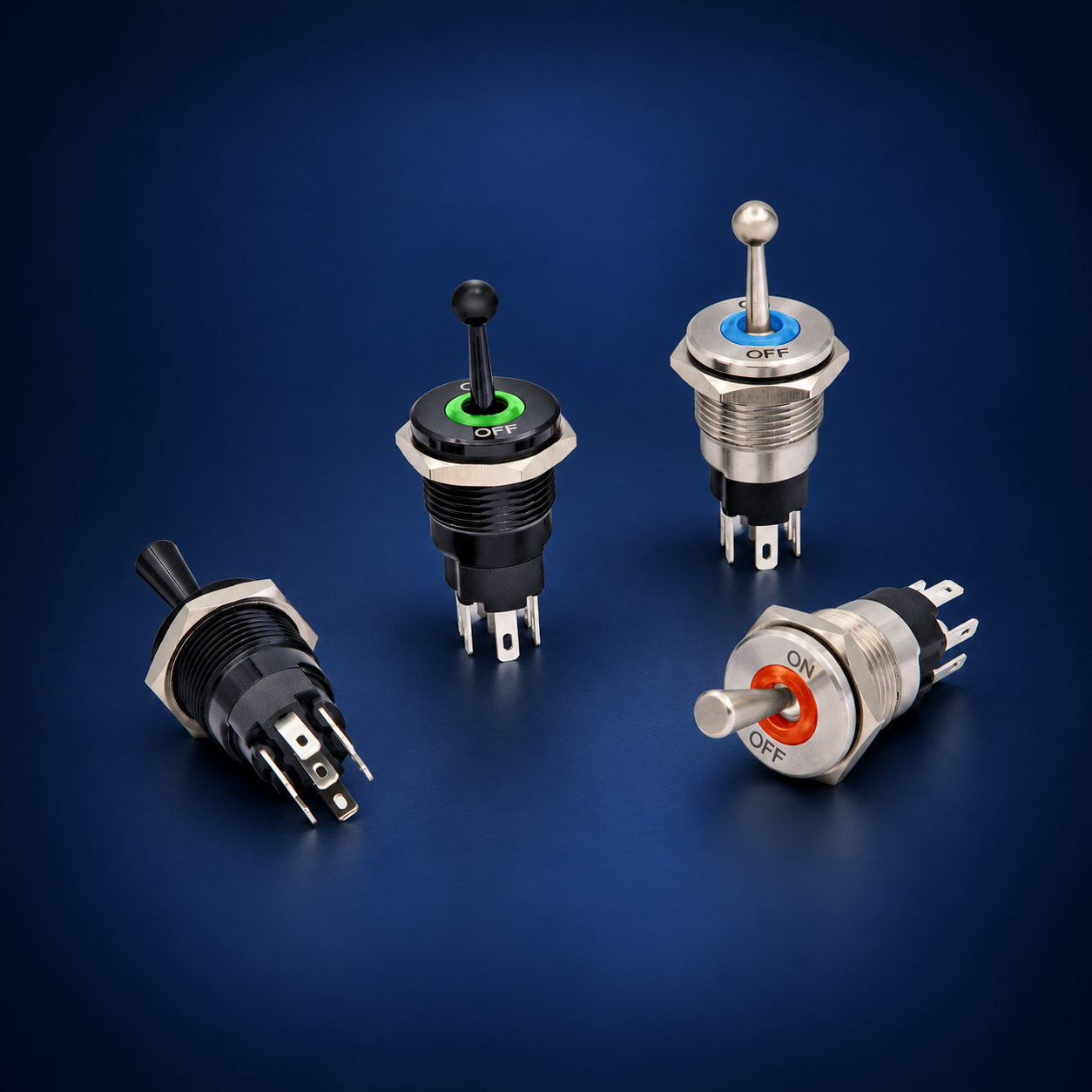
Biztonságos azonosítási és üzembe helyezési sorrend
- Definiálja a függvényt. Határozza meg, hogy az egyes aktuátorpozícióknak mit kell vezérelniük, mi történik elengedéskor, valamint mi legyen a normál állapot áramkimaradás után.
- Confirm identity. Photograph the marking and record the complete order code. Retrieve the matching current drawing rather than a family brochure.
- Isolate energy. Follow the site procedure for disconnecting and controlling hazardous energy. Prove the circuit is de-energized with appropriate equipment before touching conductors.
- Separate the component. Disconnect enough conductors to prevent parallel circuit paths from corrupting continuity measurements. Label every removed conductor.
- Map contacts. Test all terminal pairs in all positions. Repeat the sequence to detect intermittent behavior and note any spring-return action.
- Identify lamps separately. Use the published lamp diagram and voltage. Do not apply an unknown test voltage to an LED or electronic module.
- Review the load. Check normal current, inrush, AC or DC, inductive energy, switching frequency, protection and the consequence of a contact failing open or closed.
- Install mechanically. Confirm cutout, panel thickness, anti-rotation, fasteners, sealing, rear clearance, conductor support and accessible labels.
- Perform an unpowered check. Verify point-to-point wiring and insulation before energizing. Make sure unused terminals cannot contact adjacent conductive parts.
- Commission under control. Energize according to the equipment procedure, test each command and indication, then test loss and restoration of power and the credible faults identified by the risk assessment.
Load and protection boundaries
Contact ratings are conditional. A resistive laboratory load does not represent every motor, solenoid, lamp, heater, electronic power supply or capacitive input. DC interruption can sustain an arc differently from AC. Inductive loads release stored energy when opened, and cold lamps or capacitors may draw high inrush. Obtain the load data and apply only a rating that explicitly covers the intended conditions.
The switch is also not the branch-circuit protective device. Conductor size, fuse or breaker selection, short-circuit capability, grounding, insulation and enclosure protection belong to the wider equipment design. Where the operator should carry only a low-energy command, use a properly selected relay, contactor or controller input and verify the interface. Suppression components must suit the supply, load and failure behavior.
Common mistakes
- Two poles: DPDT describes contact logic, not a permission to combine unrelated voltage systems. Prevent this by completing the related verification step—confirm that the two contact sections are electrically isolated—and retaining the evidence with the machine documentation.
- Common terminals: The moving contact transfers each common between two throws. Prevent this by completing the related verification step—locate one common for each pole—and retaining the evidence with the machine documentation.
- Lever positions: ON-ON, ON-OFF-ON and momentary variants behave differently. Prevent this by completing the related verification step—record the connection matrix in every position—and retaining the evidence with the machine documentation.
- Terminal layout: A six-lug pattern can be rotated or internally arranged differently. Prevent this by completing the related verification step—use the model drawing or continuity measurements—and retaining the evidence with the machine documentation.
- Reversing logic: A wiring pattern must include safe stop, protection and prevention of simultaneous commands. Prevent this by completing the related verification step—use cross-connections only in an engineered low-voltage reversing circuit—and retaining the evidence with the machine documentation.
- Load category: A printed current alone does not define every permitted load. Prevent this by completing the related verification step—check ac or dc, resistive or inductive duty and inrush—and retaining the evidence with the machine documentation.
What to include in an RFQ
Provide the contact form, actuator positions, maintained or momentary action, center state, lamp function and voltage, supply, load category, normal and inrush current, switching frequency, panel cutout, panel thickness, rear-space limit, terminal preference, environment, ingress requirement, temperature range, vibration, required documentation, quantity and target market. Ask the supplier to return the exact contact table and dimensional drawing for the proposed order code.
Use the ONPOW industrial control product range to identify candidate families. Final selection must be based on the exact model documentation and validation in the completed assembly. For an unusual harness or control sequence, provide a terminal-view sketch and ask the supplier to mark any assumptions before samples are ordered.
Related ONPOW guides
- Toggle switch position basics
- Toggle switch and push button comparison
- Normally open and normally closed contacts
Authoritative references
- IEC 60947-5-1 control-circuit devices
- IEC 60204-1 electrical equipment of machines
- OSHA electrical safety requirements
Educational video
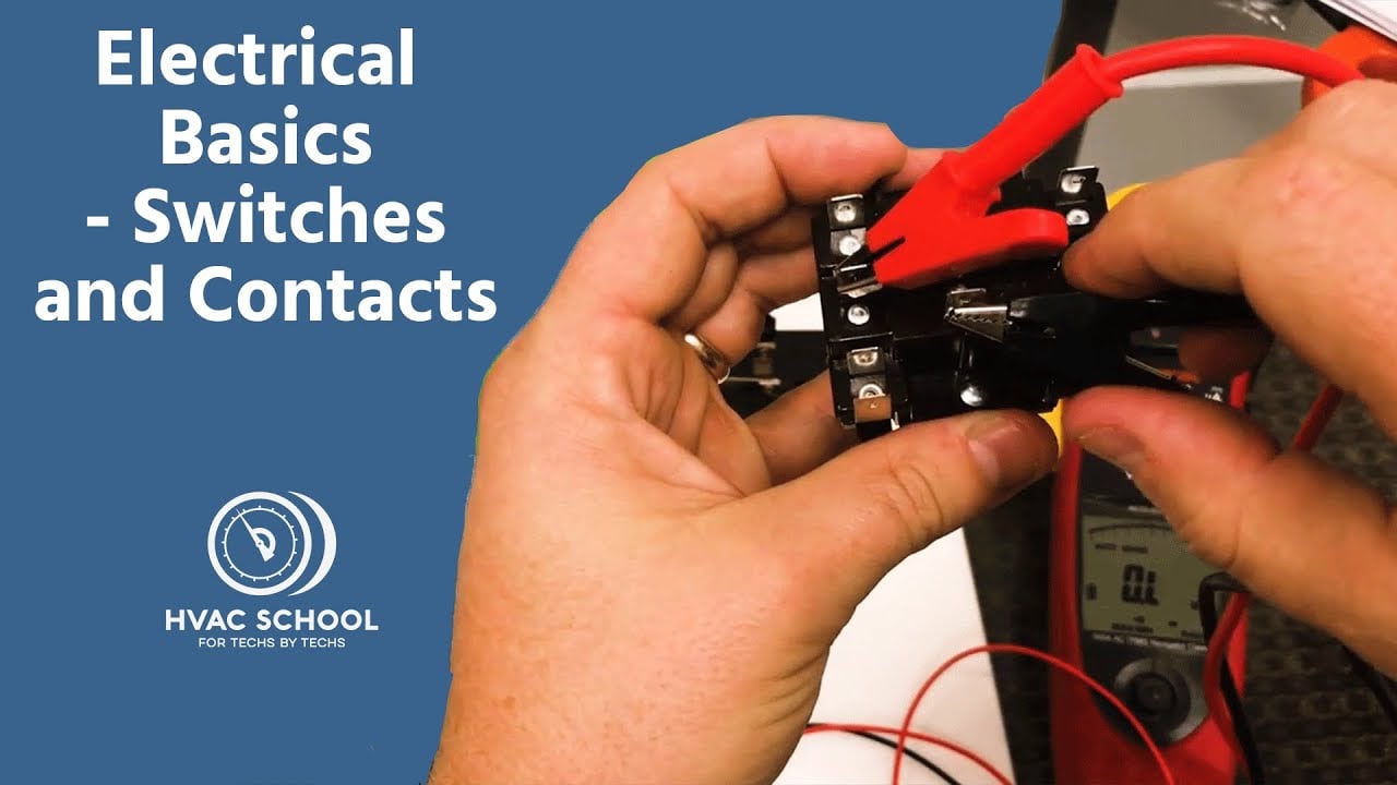
Electrical Basics – Switches and Contacts by HVAC School provides general background. The exact switch and equipment still require their own documentation and validation.
Frequently asked questions
A kapcsoló fényképe alapján megállapíthatók a kivezetések pozíciói?
Nem. Egy fotó megmutathatja a csomagolást és a kivezetések számát, de nem tudja megbízhatóan megállapítani a belső érintkező elrendezést, a nézet irányát, a lámpa áramkörét vagy a névleges értéket. Használja a pontos modellrajzot és egy izolált tesztet.
A nyomtatott amperérték minden terhelésre vonatkozik?
Nem. A megengedett érték a feszültségtől, a váltakozó (AC) vagy egyenáramtól (DC), a terhelési kategóriától, a bekapcsolási áramlökéstől, a kapcsolási frekvenciától, a hőmérséklettől és a gyártói vizsgálati feltételektől függ. Válasszon az adott alkalmazáshoz megadott névleges értékek közül.
Használható-e folytonosságmérő az érintkezők azonosítására?
Igen, ha az összes forrás el van választva, és a tárolt energia kisült. Teszteljen minden pozíciót, vegye figyelembe, hogy a lámpák áramkörei mérhetnek ellenállást, és összehasonlítsa a mátrixot a gyártói dokumentációval.
A kapcsolónak közvetlenül kell szállítania a motor- vagy szolenoidáramot?
Csak akkor, ha a pontos terhelés és a munkaciklus a dokumentált névleges értéken belül van. Nagyobb bekapcsolási áram, gyakori üzemeltetés vagy kockázatérzékeny gépek esetén gyakran a megfelelően kiválasztott relé vagy mágneskapcsoló jelenti a jobb illesztést.
Milyen információknak kell szerepelniük a végső huzalozási jegyzőkönyvben?
Rögzítse a rendelési kódot, a sorkapocs-nézet irányát, az érintkezőmátrixot, a vezetőazonosítókat, a védőeszközt, a tápellátást, a terhelést, a címkéket, a vizsgálati eredményeket, a dokumentum-revíziókat és a jóváhagyás dátumát.
Final verification rule
Approve the installation only when the exact device identity, contact matrix, lamp behavior, mechanical fit, environmental boundary, load rating, protective measures, labels and test results all agree. Resolve every discrepancy before energizing production equipment. Keep the final record with the machine so a later replacement is checked against evidence rather than appearance.



