

A double pole double throw toggle switch contains two electrically separate changeover poles operated by one lever. Six terminals are common, but their physical order is not universal. Identify both common terminals and their two throws from the exact drawing or by an isolated continuity test before connecting a control circuit. This guide explains a safe identification and verification process for engineers, panel builders, maintenance teams and buyers. It does not replace the current datasheet, machine risk assessment or locally applicable electrical requirements. The method keeps each decision traceable during purchasing, assembly, commissioning and later service.
迅速な決断
ピン数ではなく、機能から始めよ。必要な安定状態とモーメンタリ状態を書き出し、すべての接点およびランプ回路を特定してから、文書化された定格を実際の負荷に適合させよ。特定作業中は電源を絶縁状態に保て。取り付け後は、電気的状態と機械の応答の両方をテストせよ。アプリケーションが危険な動きを制御する場合は、汎用スイッチを完全な安全機能として扱うのではなく、必要な安全アーキテクチャを使用せよ。.
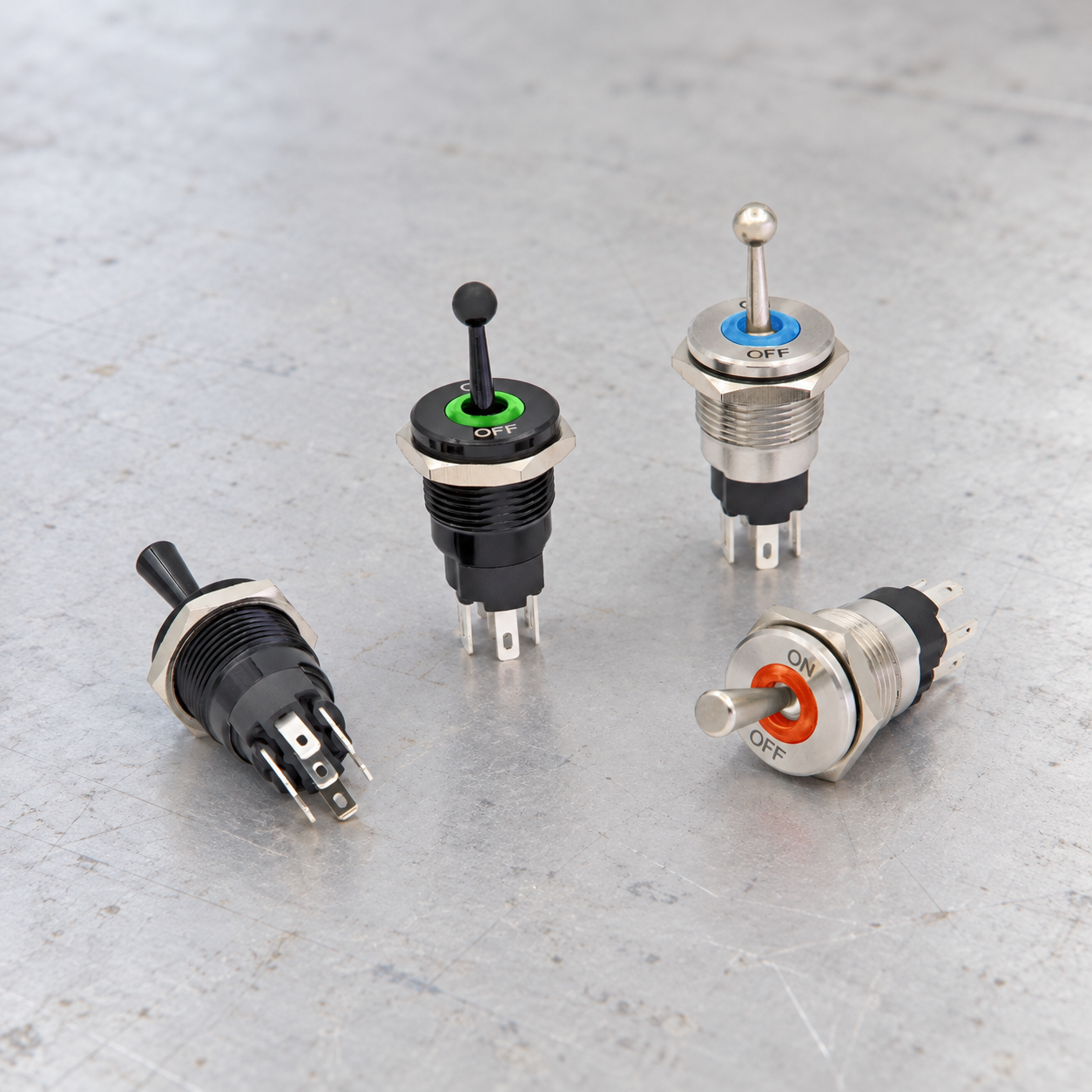
選定と配線の基準
| 決定 | 何を検証すべきか | 工学的理由 |
|---|---|---|
| Two poles | Confirm that the two contact sections are electrically isolated | DPDT describes contact logic, not a permission to combine unrelated voltage systems. |
| Common terminals | Locate one common for each pole | The moving contact transfers each common between two throws. |
| Lever positions | Record the connection matrix in every position | ON-ON, ON-OFF-ON and momentary variants behave differently. |
| Terminal layout | Use the model drawing or continuity measurements | A six-lug pattern can be rotated or internally arranged differently. |
| Reversing logic | Use cross-connections only in an engineered low-voltage reversing circuit | A wiring pattern must include safe stop, protection and prevention of simultaneous commands. |
| Load category | Check AC or DC, resistive or inductive duty and inrush | A printed current alone does not define every permitted load. |
| Circuit separation | Keep poles within insulation and system design limits | Separate poles are not automatically approved for unrelated hazardous potentials. |
| 検証 | Test continuity before energizing and function after installation | The complete machine response matters more than the lever label. |
この表は意図的に定性的なものです。数値定格、トルク、導体サイズ、絶縁距離、耐久性、および環境上の制限は、正確なデバイスの承認済み文書および完全な機器設計から取得する必要があります。似た外観のスイッチであっても、異なる内部接続を使用している場合があります。.
配線する前に接点ロジックを理解してください
ポールは、いくつの独立したコモン接点パスが連動して動作するかを表します。スローは、各コモン接点が選択できる固定接点の数を示します。これらの用語は、レバーの位置の数、位置が保持されるかモメンタリーか、切り替え時に接点がオーバーラップするか、表示灯がどのように接続されているかを示すものではありません。それらの詳細には、位置ごとの接点表が必要です。.
上部に端子を、側面にアクチュエータの位置を配置したマトリックスを描いてください。現在の図面または独立した測定によってサポートされている接続のみマークしてください。「アクチュエータを上にした背面端子ビュー」などの明確な視点方向を含めてください。この簡単な記録により、組み立て時やその後のサービス時に、ミラーリングされた図面、回転した部品、ハーネスのキャビティ番号が混同されるのを防ぎます。.
Two poles
確認事項: Confirm that the two contact sections are electrically isolated. DPDT describes contact logic, not a permission to combine unrelated voltage systems. The engineering record should name the exact order code, drawing revision, supply, load and operating state used for the decision. Check the component in its installed orientation because panel thickness, wire routing, adjacent hardware and actuator access can change the result.
確認方法: 現在のメーカー製接点図と絶縁導通テストを比較してください。動作前、すべての保持位置、およびすべてのモーメンタリ位置からの解放後に測定された状態を記録してください。文書と測定結果が一致しない場合は、電源を入れる前に作業を中断し、不一致を解消してください。端子の機能は、端子の位置、金属の色、または類似の見た目のスイッチの図から推測しないでください。.
Common terminals
確認事項: Locate one common for each pole. The moving contact transfers each common between two throws. The engineering record should name the exact order code, drawing revision, supply, load and operating state used for the decision. Check the component in its installed orientation because panel thickness, wire routing, adjacent hardware and actuator access can change the result.
確認方法: 現在のメーカー製接点図と絶縁導通テストを比較してください。動作前、すべての保持位置、およびすべてのモーメンタリ位置からの解放後に測定された状態を記録してください。文書と測定結果が一致しない場合は、電源を入れる前に作業を中断し、不一致を解消してください。端子の機能は、端子の位置、金属の色、または類似の見た目のスイッチの図から推測しないでください。.
Lever positions
確認事項: Record the connection matrix in every position. ON-ON, ON-OFF-ON and momentary variants behave differently. The engineering record should name the exact order code, drawing revision, supply, load and operating state used for the decision. Check the component in its installed orientation because panel thickness, wire routing, adjacent hardware and actuator access can change the result.
確認方法: 現在のメーカー製接点図と絶縁導通テストを比較してください。動作前、すべての保持位置、およびすべてのモーメンタリ位置からの解放後に測定された状態を記録してください。文書と測定結果が一致しない場合は、電源を入れる前に作業を中断し、不一致を解消してください。端子の機能は、端子の位置、金属の色、または類似の見た目のスイッチの図から推測しないでください。.
Terminal layout
確認事項: Use the model drawing or continuity measurements. A six-lug pattern can be rotated or internally arranged differently. The engineering record should name the exact order code, drawing revision, supply, load and operating state used for the decision. Check the component in its installed orientation because panel thickness, wire routing, adjacent hardware and actuator access can change the result.
確認方法: 現在のメーカー製接点図と絶縁導通テストを比較してください。動作前、すべての保持位置、およびすべてのモーメンタリ位置からの解放後に測定された状態を記録してください。文書と測定結果が一致しない場合は、電源を入れる前に作業を中断し、不一致を解消してください。端子の機能は、端子の位置、金属の色、または類似の見た目のスイッチの図から推測しないでください。.
Reversing logic
確認事項: Use cross-connections only in an engineered low-voltage reversing circuit. A wiring pattern must include safe stop, protection and prevention of simultaneous commands. The engineering record should name the exact order code, drawing revision, supply, load and operating state used for the decision. Check the component in its installed orientation because panel thickness, wire routing, adjacent hardware and actuator access can change the result.
確認方法: 現在のメーカー製接点図と絶縁導通テストを比較してください。動作前、すべての保持位置、およびすべてのモーメンタリ位置からの解放後に測定された状態を記録してください。文書と測定結果が一致しない場合は、電源を入れる前に作業を中断し、不一致を解消してください。端子の機能は、端子の位置、金属の色、または類似の見た目のスイッチの図から推測しないでください。.
Load category
確認事項: Check AC or DC, resistive or inductive duty and inrush. A printed current alone does not define every permitted load. The engineering record should name the exact order code, drawing revision, supply, load and operating state used for the decision. Check the component in its installed orientation because panel thickness, wire routing, adjacent hardware and actuator access can change the result.
確認方法: 現在のメーカー製接点図と絶縁導通テストを比較してください。動作前、すべての保持位置、およびすべてのモーメンタリ位置からの解放後に測定された状態を記録してください。文書と測定結果が一致しない場合は、電源を入れる前に作業を中断し、不一致を解消してください。端子の機能は、端子の位置、金属の色、または類似の見た目のスイッチの図から推測しないでください。.
Circuit separation
確認事項: Keep poles within insulation and system design limits. Separate poles are not automatically approved for unrelated hazardous potentials. The engineering record should name the exact order code, drawing revision, supply, load and operating state used for the decision. Check the component in its installed orientation because panel thickness, wire routing, adjacent hardware and actuator access can change the result.
確認方法: 現在のメーカー製接点図と絶縁導通テストを比較してください。動作前、すべての保持位置、およびすべてのモーメンタリ位置からの解放後に測定された状態を記録してください。文書と測定結果が一致しない場合は、電源を入れる前に作業を中断し、不一致を解消してください。端子の機能は、端子の位置、金属の色、または類似の見た目のスイッチの図から推測しないでください。.
検証
確認事項: Test continuity before energizing and function after installation. The complete machine response matters more than the lever label. The engineering record should name the exact order code, drawing revision, supply, load and operating state used for the decision. Check the component in its installed orientation because panel thickness, wire routing, adjacent hardware and actuator access can change the result.
確認方法: 現在のメーカー製接点図と絶縁導通テストを比較してください。動作前、すべての保持位置、およびすべてのモーメンタリ位置からの解放後に測定された状態を記録してください。文書と測定結果が一致しない場合は、電源を入れる前に作業を中断し、不一致を解消してください。端子の機能は、端子の位置、金属の色、または類似の見た目のスイッチの図から推測しないでください。.
安全な識別と試運転のシーケンス
- 関数を定義する。. 各アクチュエータの位置が何を指令すべきか、解放時にはどうなるか、そして電源喪失後の通常状態がどうでなければならないかを述べてください。.
- 身元を確認する。. マーキングを撮影し、完全な注文コードを記録してください。ファミリパンフレットではなく、一致する最新の図面を取得してください。.
- エネルギーを隔離する. サイトの手順に従って危険なエネルギーを遮断し、制御してください。導体に触れる前に、適切な機器を使用して回路の通電が停止していることを証明してください。.
- コンポーネントを分離してください。. 並列回路の経路が導通測定に影響を与えないよう、十分な数の導体を取り外してください。取り外した導体にはすべてラベルを貼ってください。.
- 連絡先をマップする. すべての位置ですべての端子ペアをテストします。断続的な動作を検出するためにシーケンスを繰り返し、スプリングリターン動作に注意してください。.
- ランプを個別に特定してください。. 公開されているランプの図と電圧を使用してください。未知のテスト電圧をLEDや電子モジュールに印加しないでください。.
- 負荷を確認する。. 通常電流、突入電流、ACまたはDC、誘導性エネルギー、スイッチング周波数、保護、および接点が開放または閉路状態で故障した場合の影響を確認してください。.
- 機械的に取り付けてください。. 切り欠き、パネル厚、回り止め、締結部品、シーリング、背面クリアランス、導体サポート、およびアクセス可能なラベルを確認してください。.
- 非通電チェックを実施してください。. 通電する前に、ポイント間配線と絶縁を確認してください。未使用の端子が隣接する導電部に接触しないようにしてください。.
- 委員会は管理下にあります。. 機器手順書に従って電源を投入し、各指令と表示をテストした後、電力の喪失と復旧、およびリスクアセスメントで特定された想定しうる不具合をテストしてください。.
負荷と保護の境界線
接点定格は条件付きです。抵抗性の実験室負荷は、すべてのモーター、ソレノイド、ランプ、ヒーター、電子電源、または容量性入力を代表するものではありません。直流(DC)の遮断は、交流(AC)とは異なるアークを持続させる可能性があります。誘導性負荷は開放時に蓄積されたエネルギーを放出し、冷えたランプやコンデンサは高い突入電流を引き起こす可能性があります。負荷データを取得し、意図した条件を明示的に網羅する定格のみを適用してください。.
スイッチも分岐回路保護装置ではありません。導体のサイズ、ヒューズまたは遮断器の選定、短絡容量、接地、絶縁、および筐体の保護は、より広範な機器設計に属するものです。オペレータが低エネルギーの指令のみを伝達すべき場所では、適切に選定されたリレー、接触器、またはコントローラ入力を使用し、インターフェースを確認してください。サプレッション部品は、電源、負荷、および故障時の挙動に適している必要があります。.
よくある間違い
- Two poles: DPDT describes contact logic, not a permission to combine unrelated voltage systems. Prevent this by completing the related verification step—confirm that the two contact sections are electrically isolated—and retaining the evidence with the machine documentation.
- Common terminals: The moving contact transfers each common between two throws. Prevent this by completing the related verification step—locate one common for each pole—and retaining the evidence with the machine documentation.
- Lever positions: ON-ON, ON-OFF-ON and momentary variants behave differently. Prevent this by completing the related verification step—record the connection matrix in every position—and retaining the evidence with the machine documentation.
- Terminal layout: A six-lug pattern can be rotated or internally arranged differently. Prevent this by completing the related verification step—use the model drawing or continuity measurements—and retaining the evidence with the machine documentation.
- Reversing logic: A wiring pattern must include safe stop, protection and prevention of simultaneous commands. Prevent this by completing the related verification step—use cross-connections only in an engineered low-voltage reversing circuit—and retaining the evidence with the machine documentation.
- Load category: A printed current alone does not define every permitted load. Prevent this by completing the related verification step—check ac or dc, resistive or inductive duty and inrush—and retaining the evidence with the machine documentation.
見積依頼書(RFQ)に含めるべき内容
接点構成、アクチュエータ位置、モメンタリまたはオルタネイト動作、センター状態、ランプ機能と電圧、電源、負荷カテゴリ、定格電流および突入電流、開閉頻度、パネルカットアウト、パネル厚、背面スペースの制限、端子の希望、使用環境、防水・防塵要件、温度範囲、耐振性、必要書類、数量、およびターゲット市場をご提供ください。提案された型番について、正確な接点表と外形図を返送するようサプライヤーにご依頼ください。.
使用する ONPOWの産業用制御製品群 候補のファミリを特定するため。最終選定は、完成したアセンブリにおける正確なモデル文書と検証に基づく必要があります。特殊なハーネスまたは制御シーケンスの場合は、端子ビューのスケッチを提供し、サンプルの発注前にサプライヤーに前提条件の確認を依頼してください。.
関連するONPOWガイド
信頼できる参考文献
教育ビデオ
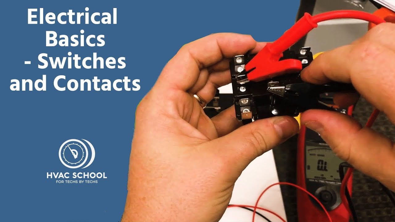
HVAC Schoolの「Electrical Basics – Switches and Contacts」は一般的な背景知識を提供するものですが、正確なスイッチや機器については、それぞれ個別の資料および検証が必要です。.
よくある質問
このトグルスイッチの写真から端子の位置を特定できますか?
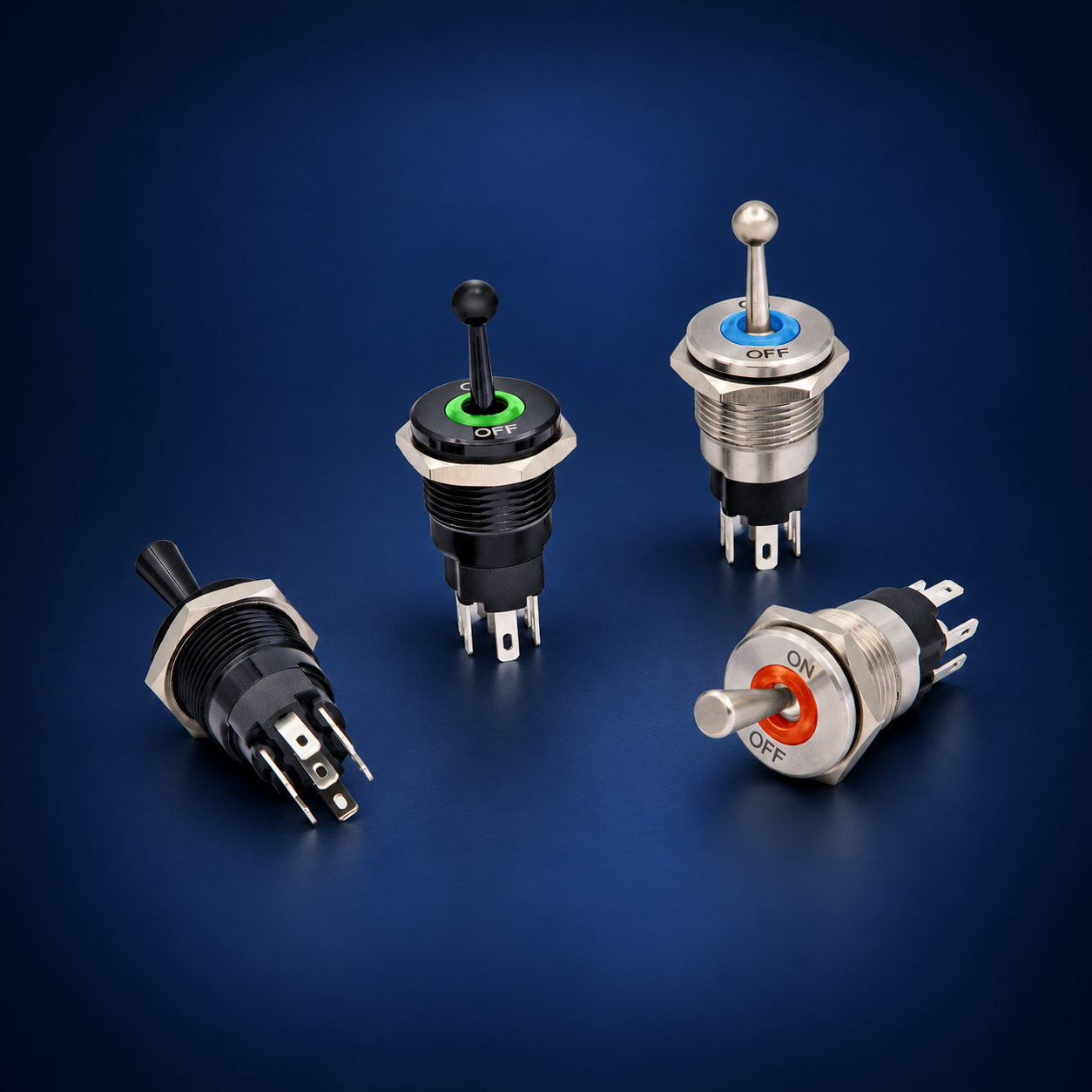
いいえ。写真はパッケージや端子の数を示すことはできますが、内部の接点配置、視覚的向き、ランプ回路、定格を確実に立証することはできません。正確な型番の図面と、単独のテストを使用してください。.
印刷されたアンペア値はすべての負荷に適用されますか?
いいえ。許容値は、電圧、ACまたはDC、負荷カテゴリ、突入電流、スイッチング周波数、温度、およびメーカーの試験条件によって異なります。実際のアプリケーションに記載されている定格から選択してください。.
導通テスターを使用して接点を特定することはできますか?
はい、すべての電源が切り離され、蓄えられたエネルギーが放出されている場合です。すべての位置でテストを行い、ランプ回路が抵抗値を示す場合があることを認識し、マトリックスとメーカーのドキュメントを比較してください。.
スイッチはモーターまたはソレノイドの電流を直接遮断すべきですか?
正確な負荷とデューティが記載された定格内である場合に限ります。より大きな突入電流、頻繁な作動、またはリスクに敏感な機械に対しては、適切に選択されたリレーやコンタクタの方がより良いインターフェースであることがよくあります。.
最終的な配線記録にはどのような情報が含まれますか?
発注コード、端子ビューの方向、コンタクトマトリックス、導体識別子、保護装置、電源、負荷、ラベル、テスト結果、文書改訂、および承認日を記録してください。.
最終検証ルール
正確なデバイス識別、コンタクトマトリックス、ランプの動作、機械的適合性、環境境界、定格荷重、保護対策、ラベル、およびテスト結果のすべてが一致する場合にのみ、取り付けを承認してください。生産設備の通電前に、すべての不一致を解消してください。後日の交換時に見た目ではなく証拠に基づいて確認できるように、最終記録を機械と一緒に保管してください。.



