

An RJ45 panel-mount connector provides an accessible physical network connection at an enclosure boundary. Select it by the complete front-to-rear arrangement, required Ethernet performance, shielding approach, cable routing and environmental condition. A socket that accepts an RJ45 plug does not automatically prove a working industrial network, a particular category, Power over Ethernet capability or enclosure protection. Qualify the finished channel with the actual equipment and cable arrangement, and keep network configuration separate from the mechanical connector check. This makes a service port easier to maintain without treating physical fit as complete network acceptance.
Define the connection’s purpose and ownership
Start by identifying the equipment at both ends. The port may connect a maintenance laptop, link a controller to a switch or expose an approved diagnostic interface. Record whether it is a temporary service connection or a permanent network connection. Different uses can require different access rules, labels and protection arrangements.
Assign responsibility for network configuration and physical installation. A panel builder can supply a mechanically correct port while the equipment owner controls addresses, access rights and permitted devices. Put those boundaries in the commissioning plan so a link failure is investigated by the right people rather than blamed immediately on the connector.
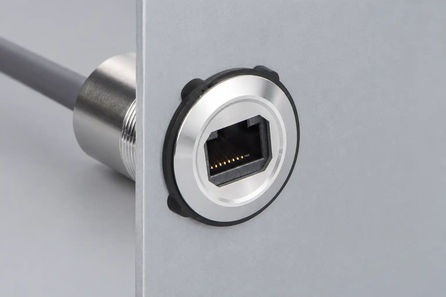
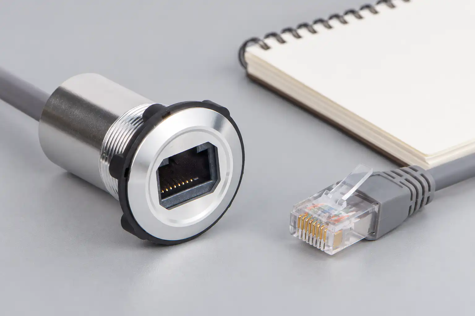
The ONPOW RJ45-01-(BK) product page provides a real panel-connector reference. Obtain the exact assembly drawing and performance statement for the ordered version. Its photograph shows a physical interface and mounting form; it does not independently establish network category, shielding continuity, PoE support or environmental ratings.
Draw the complete network path
Document the equipment port, internal cable, panel connector, external cable and remote equipment. Identify each plug, receptacle and any coupler in the path. Record the final cable route and service loop. A bench test using one short lead does not represent a cabinet installation containing several additional interfaces.
Confirm whether the assembly is a passive connection or contains active network equipment. A passive panel adapter does not assign an address, provide switching functions or convert an unrelated protocol into Ethernet. If the application needs an active function, identify the corresponding equipment and its documentation separately.
The IEEE 802.3 working group is a primary reference for the Ethernet standards family. Use the applicable standards and equipment requirements for the actual network. A generic “RJ45” description is a connector-form description, not a complete performance specification for the assembled channel.
Separate continuity, link and application performance
A wiring check can establish that conductors connect as intended under the test method. A link indication shows a different level of evidence. Neither alone proves that the required maintenance or production application will perform reliably. Plan these checks as separate stages with clearly stated acceptance criteria.
For a service port, the useful end result may be a successful authorised diagnostic session. For a permanent machine link, it may include application communication under representative operation. Record the actual task and equipment state. Do not conclude that a connection is fully accepted merely because an indicator light turns on.
Keep test tools appropriate to the requirement. A simple continuity tester cannot establish every channel-performance characteristic. If category or channel certification is required, use the agreed standard, suitable equipment and competent personnel. Save the report with the installed cable identities and connector configuration.
Use a configuration checklist
This qualitative table defines the information needed for a selection decision. It does not assign performance values to the referenced ONPOW connector.
| Item | Question to resolve | Acceptance evidence |
|---|---|---|
| Network task | Which devices and application must communicate? | Approved connection diagram and functional result |
| Connector arrangement | What is fitted at the front and rear? | Exact assembly drawing and order code |
| Channel performance | What performance does the complete path require? | Relevant specification and agreed channel test |
| Shielding | How is the installed shield path handled? | Documented cabinet bonding and cable design |
| Power over Ethernet | Is power required through this path? | Explicit assembly and equipment support |
| Panel installation | Are cutout, thickness and rear clearance correct? | Finished-panel fit inspection |
| Környezet | Which open, capped or connected condition applies? | Configuration-specific protection evidence |
Review shielding as an installed system
Determine the shielding arrangement required by the equipment and cabinet design. A metal front bezel does not automatically prove the intended shield connection. Ask for the assembly’s construction information and review how it is installed, including the cable shield and any required bonding interface.
Do not improvise a grounding rule based only on the connector photograph. The correct arrangement depends on the network equipment, cable system, cabinet design and applicable requirements. Keep the decision with the responsible electrical and network engineers. Record the approved approach so maintenance replacements preserve it.
Route the data cable with regard to the machine’s electrical layout and equipment instructions. Avoid physical damage, sharp bends and strain at the connector. Where interference is suspected, investigate the complete installation rather than changing the panel socket repeatedly without evidence. Preserve the route and equipment state in the troubleshooting record.
Check PoE explicitly when it is required
An Ethernet data path and a Power over Ethernet application present related but distinct requirements. Confirm that the exact connector assembly, cable path and equipment support the intended power function. Do not infer support from the presence of eight contacts or from a successful unpowered network connection.
Identify the actual power-sourcing and powered equipment and obtain their requirements. Include the intended operating conditions in the enquiry. If the assembly documentation does not address the required power function, request clarification or choose a documented configuration before installation.
Keep the acceptance test within an approved procedure and use suitable equipment. A device powering up once does not establish every required operating condition. Record the complete combination that was tested so later cable or device substitutions can be assessed against the same requirement.
Plan panel fit and environmental conditions
Use the approved drawing for the cutout, mounting stack and retaining hardware. Include the finished panel thickness, coating and any gasket. Reserve enough rear space for the internal connection and cable bend. A connector can fit the hole while leaving the rear cable under continuous mechanical stress.
Review protection in the exact operating state: open, capped or connected. The IEC 60529 publication page identifies the ingress-protection framework, but it does not certify an arbitrary installation. Ask the supplier what configuration the evidence covers and assess the complete enclosure accordingly.
The broader control-panel layout guide helps coordinate access and clearances. Keep network service plugs away from positions where they obstruct an emergency operator or catch on moving equipment. Check cap access and normal service handling in the final panel layout.
Make the service interface understandable
Label the port with its approved purpose and, where relevant, the equipment or network it connects to. Avoid a generic label that encourages technicians to plug into the wrong network. Keep port identification consistent with the schematic, service manual and network records.
An accessible network socket is also a system access point. The equipment owner should define authorised users and devices. NIST SP 800-82 provides broader operational-technology security guidance. The physical connector does not enforce network permissions by itself.
Compare this interface with the panel USB service port and push button connector assemblies. These are complementary maintenance interfaces with different signal and qualification requirements. Their shared panel-mount appearance does not make them interchangeable.
Diagnose failures without confusing layers
If there is no connection, first confirm the intended devices and network path. Check the approved cable set and physical connection without changing several variables simultaneously. Record whether the symptom follows one cable, one panel assembly or one equipment port. A known comparison arrangement can help isolate the problem when used under the approved test plan.
If a physical link exists but the application fails, investigate the application and network configuration as well as the channel. Preserve error messages, timing and equipment state. Replacing the connector may temporarily coincide with recovery without proving the connector caused the fault.
For intermittent failures, document movement, door position and environmental conditions associated with the symptom. Do not repeatedly bend the cable to make the fault disappear before recording it. Preserve suspect assemblies and their identities for supplier investigation, especially where a terminal or cable strain issue is suspected.
Freeze the qualified configuration
Before production release, record the connector code, drawing revision, internal cable, approved external cable requirements, equipment identities and test results. Confirm that maintenance staff can replace the assembly without guessing the rear arrangement from the visible socket.
A later change to cable construction, connector variant or equipment can affect the qualified path. Apply the project’s change-control process and repeat the relevant checks. Send ONPOW the complete connection diagram, mounting constraints, required network performance and any PoE or environmental requirement for configuration confirmation.
Frequently asked questions
Does an RJ45 socket guarantee a particular Ethernet speed?
No. Confirm the performance of the complete assembly and channel with the intended equipment and cable arrangement.
Is a continuity test enough for network acceptance?
No. Continuity, link establishment and application performance are different checks. Use the test method appropriate to each requirement.
Does a metal connector body prove shielding continuity?
No. The assembly construction and installed shield path must be documented and checked against the cabinet design.
Can PoE capability be assumed from a working data link?
No. Obtain explicit support for the exact assembly and equipment, and qualify the required power function under the approved procedure.
Further learning
A neutral educational explanation of Ethernet data organisation, complementing the distinction between a physical panel socket and a working network path.



