

A pilot light schematic symbol represents an electrical signalling function, not the complete physical lamp or its supply rating. In many control drawings a lamp is shown as a circle with crossing lines, while a discrete LED uses a diode symbol with outward light arrows. The drawing’s declared symbol convention and legend govern the exact graphic. Read the symbol together with its device tag, supply annotation, terminals, and cross-references. A symbol alone cannot tell you that a panel indicator accepts AC, DC, a particular voltage, or both polarities. Those details come from the selected product and circuit documentation.
Distinguish a schematic symbol from a panel icon
A schematic shows how electrical elements are connected. A panel label or equipment icon explains what an operator should understand or do. The two can refer to the same lamp but serve different purposes. A power icon on the cabinet does not establish the indicator’s internal electrical circuit.
The IEC 60617 database is the IEC resource for graphical symbols used in electrotechnical diagrams, including lamps and signalling devices. The equipment-symbol system is a separate context; the IEC technical committee’s equipment-symbol guidance explains that use. Do not exchange those symbol families without checking the drawing requirements.
The goal when reviewing an ONPOW panel indicator is to connect three records: the schematic device, the purchased part, and the operator-visible function. Each should identify the same installation without making unsupported assumptions from the other two.
Recognize the common lamp and LED conventions
A conventional general lamp symbol often uses a circle containing an X, connected into the circuit by conductor lines. A discrete LED is commonly represented by a diode graphic with arrows pointing away to indicate light emission. These are visual starting points, not substitutes for the approved project symbol library.
A complete panel indicator may contain more than a discrete LED. It can include current-limiting, rectification, or other internal functions specific to its design. The schematic may represent it as a complete signalling device rather than showing every internal element. Use the part annotation and product drawing to determine what has been abstracted.
| Drawing feature | What it tells the reviewer | What it does not establish alone |
|---|---|---|
| General lamp symbol | A light-emitting signalling function is represented | Exact lamp technology or supply rating |
| Discrete LED symbol | The shown element is an LED with an indicated electrical orientation | Suitability of a complete panel lamp for that connection |
| Device tag | Reference identity in the project documentation | A universal manufacturer part number |
| Supply annotation | Intended circuit supply or design requirement | Confirmation that the ordered variant matches |
| Terminal designation | Connection reference on the drawing | Physical location without the product terminal map |
| Color or function note | Intended visual message | Proof of a complete alarm strategy |
The table describes drawing interpretation. For an exact standards graphic, use the project’s authorized symbol library and the referenced standard rather than redrawing a catalogue icon by eye.
Read the device tag with the parts list
Tags such as a project-specific lamp designation link the schematic to a device schedule or bill of materials. Do not assume that one prefix convention applies to every drawing set. Read the legend and the document’s reference-designation method.
The parts list should identify the exact manufacturer, model, supply variant, lens or emitted color, mounting requirements, and terminal form. A tag that maps only to indicator light is incomplete for purchasing. The schematic may be electrically correct while the selected part has the wrong supply or physical size.
Keep the drawing revision and parts-list revision aligned. If a lamp changes from one supply variant to another, update the relevant circuit and device records through the project’s change process. A drawing note cannot make an incorrectly purchased lamp compatible with the supply.
Determine the supply from the circuit and product data
Trace both conductors or the relevant reference connections. Identify the supply source, protective arrangement, switching element, and return. A two-terminal lamp symbol does not indicate whether the internal circuit accepts AC or DC. Nor does it imply that both polarity orientations are permitted.
For a DC indicator, use the manufacturer’s terminal and polarity information. Some complete indicators have internal arrangements that change the wiring requirements, but those capabilities must be declared for the exact variant. Do not infer them from a similar lamp or from the appearance of its front lens.
Read 12V versus 24V indicator-light selection for that supply comparison and the 120V AC indicator-light guide for a different voltage-specific context. These separate articles provide supply questions that a general symbol cannot answer.
Separate a command indication from confirmed machine status
A lamp connected to a controller output may indicate that a command has been issued. It may not prove that the motor, valve, or mechanism reached the commanded state. A drawing should make clear whether the signal comes from a command bit, auxiliary contact, position feedback, or another source.
For example, a lamp described as run can be misleading if it only follows a run command while the drive remains stopped. The designer should define the intended meaning and the source of evidence. This is a circuit and control-narrative question, not a property of the lamp graphic.
Use clear panel labels and consistent terminology in the schematic and operating instructions. The indicator-light color guide discusses visual meaning; color should supplement the documented function rather than substitute for a precise label.
Show lamp and switch functions separately when needed
An illuminated push button combines an operator input with an indication, but the lamp circuit and contact circuit can be distinct. A drawing needs to identify both functions and their relationships. Do not connect the illumination supply by copying the contact terminal numbers.
The indicator light versus illuminated push-button guide helps decide which physical operator device serves the task. The schematic must still represent the exact selected circuit, including any shared connections that the manufacturer declares.
A selector or key switch with illumination adds another possible source of confusion: the light may indicate power availability, selected mode, or feedback from the control system. State the meaning in the design record. It is not automatically determined by the lamp’s physical location inside the operator.

Include cross-references that permit a complete review
A lamp may be drawn on a different page from its controller output, supply source, or related contact. Cross-references should let the reviewer trace the circuit without guessing where it continues. Wire numbers and terminal-block references should also match the field wiring schedule.
When a contact or output drives several indicators, check the actual load and the receiving devices. A simplified drawing can obscure multiple connected loads, supply branches, or references. Compare the schematic with the final equipment wiring and parts list during commissioning.
The IEC 60947-5-1 publication information provides the standards scope for electromechanical control-circuit devices and associated signalling. It does not identify a product’s voltage from its schematic symbol. Keep those standards references separate from model-specific installation data.
Check the physical indicator against the document
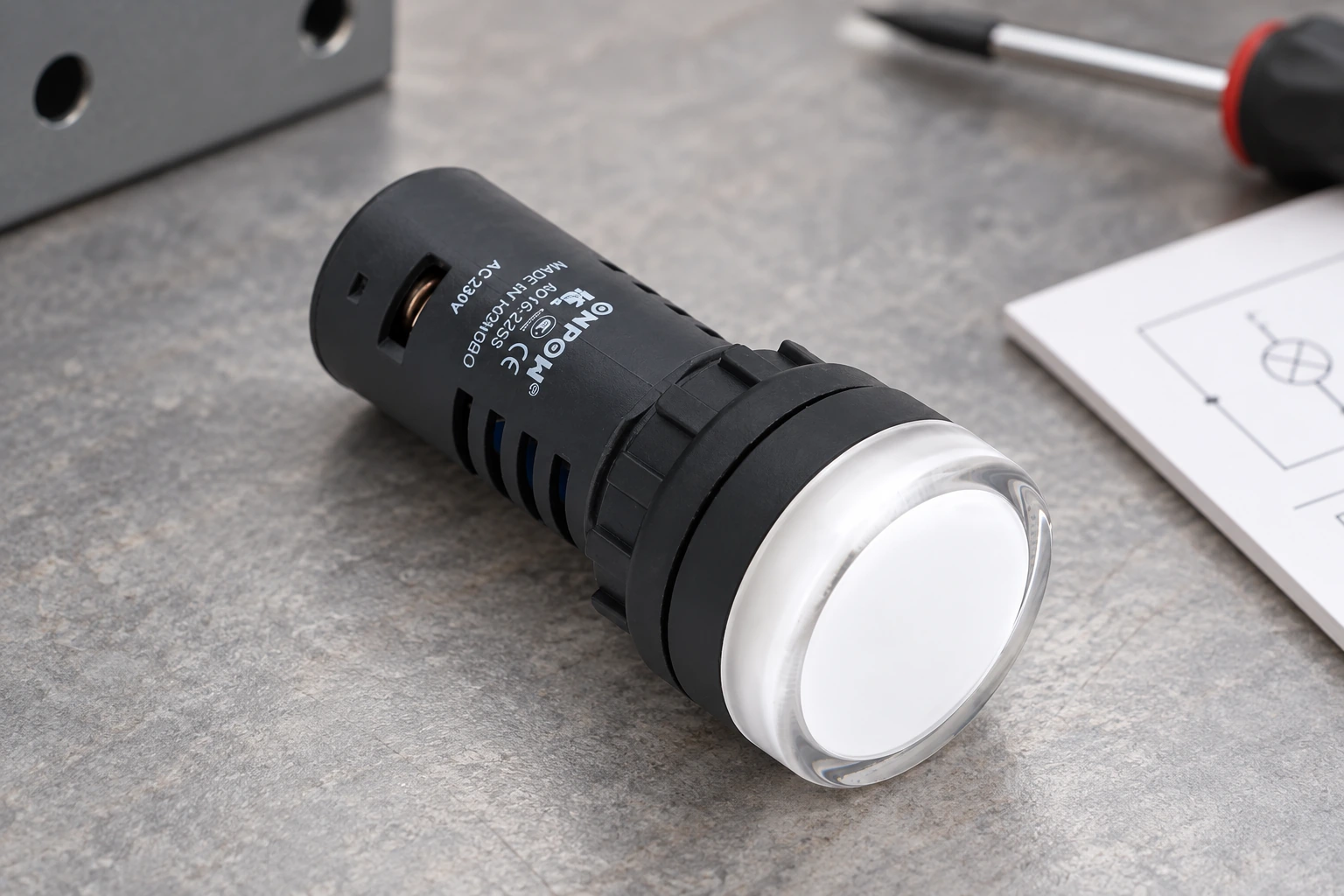
The article’s images use a real ONPOW AD16-22D product reference. Its lens and body help illustrate the physical device, but the schematic must identify the ordered variant. Do not use a photograph to assign a supply rating, terminal identity, or flashing capability.
Verify mounting dimensions, front appearance, terminal form, access, environment, and supply against the current product documentation. The lamp’s operator-visible color and the drawing’s color note should agree. Where multiple variants share a body, control the full suffix in purchasing and maintenance records.
If the installed lamp does not match the parts list, investigate the substitution before changing the drawing to make it look correct. The circuit’s electrical suitability and intended indication need confirmation first.
Review and verify through the approved procedure
Electrical inspection of installed panels requires qualified personnel and appropriate work practices. Do not test a lamp by applying an assumed supply based on a symbol. In United States workplaces, relevant electrical-work requirements include 29 CFR 1910.333.
A document review can compare symbol, tag, part, supply, terminal map, source signal, and panel function before the equipment is energized. During authorized commissioning, confirm the displayed state for each intended condition and verify any lamp-test function. A lamp that illuminates proves its immediate visible response, not that every upstream machine condition is correct.
Record mismatches and update the affected approved documents. A useful handover includes a traceable device schedule, clear schematic references, and an indication-state table so that later maintenance does not have to infer the function from a colored lens.
Educational video
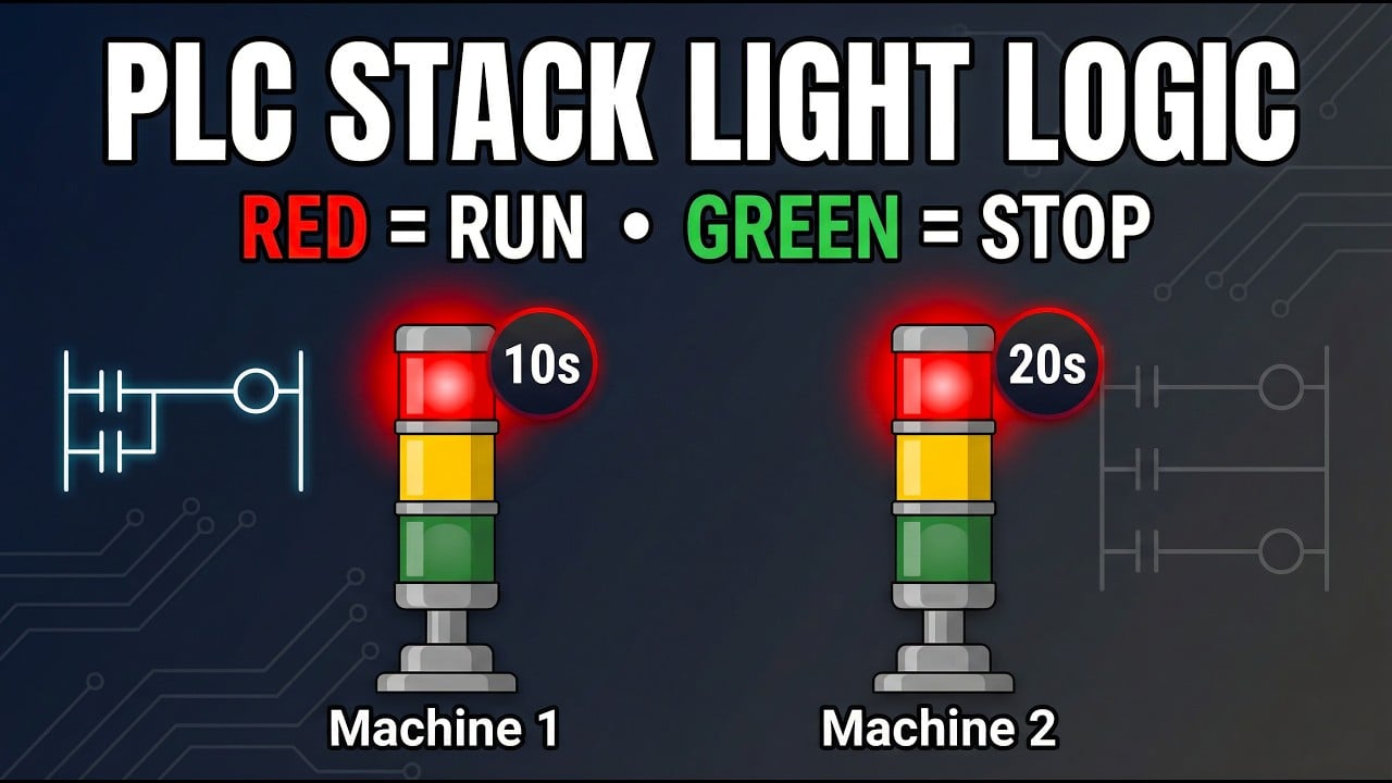
PLC Stack Light Logic by Instrumentation Tools. General educational background. Use the selected product drawing and the machine design for the actual circuit and installation. Watch on YouTube.
Frequently asked questions
Is every circle with an X an indicator lamp?
It is a common lamp convention, but the project’s symbol standard and legend govern interpretation. Confirm the surrounding circuit and device annotation.
Does an LED symbol mean a panel lamp needs an external resistor?
Not automatically. A complete panel indicator can include internal circuitry. Use its exact supply and installation data rather than assuming it is a bare LED.
Can the symbol tell me whether the lamp is AC or DC?
No. Read the supply annotations, circuit, parts list, and manufacturer’s data for the selected variant.
Is a run lamp proof that the machine is moving?
Only if the design defines and verifies that meaning. A lamp may follow a command rather than actual movement or position feedback.
What should be recorded for an illuminated push button?
Identify both the lamp circuit and contact function, their terminal maps and supplies, the operator label, and the exact ordered device variant.



