

Push button panel thickness is the finished thickness of the panel and approved accessories that the mounting system must clamp. It is different from the cutout diameter and from the space required behind the panel. A button can pass through the hole yet fail to retain correctly because its clamping range does not cover the installed stack. Before ordering, compare the exact model drawing with the panel, coating, seal, legend plate and retaining hardware. Do not infer an allowable thickness from nominal button size or visible thread length alone. This guide explains how to check the complete mounting interface before production.
Separate the three dimensions that determine fit
Cutout size controls whether the mounting body enters the panel and whether required locating features align. Panel thickness controls the axial stack captured between the front flange and retaining system. Rear clearance controls the space needed for the body, terminals, connectors, wire bends and service tools. These dimensions interact, but none substitutes for the others.
For example, a design may have the correct nominal hole size and adequate cabinet depth, while a thick decorative front plate prevents the nut from reaching its approved position. Another design may clamp correctly but place the connector against the cabinet wall. Record all three checks separately in the mechanical review rather than marking the switch as fitting after a single trial insertion.
The Panduan tombol dorong yang dipasang di panel provides the wider selection framework. Use this thickness review with the rear clearance guide when approving a shallow enclosure or a layered front panel.
Start with the exact mounting system
Identify whether the selected device uses a threaded barrel and nut, a clip, a snap-in feature or another retaining arrangement. Different systems can have different installation limits and required accessories. Even within a product family, a short body or alternative head construction may change the approved mounting configuration. Confirm the complete ordering code before using a drawing.
For a threaded assembly, identify the surfaces that clamp the panel and the location of the seal. For a snap-in assembly, identify the retaining features and the specified panel conditions they depend on. Do not substitute a general threaded-barrel calculation for a clip manufacturer’s stated range. If a product drawing omits a needed dimension, request clarification rather than estimating from a photograph.
The illustrated ONPOW LAS1GQ product shows a threaded metal construction. It is a visual reference for discussing the interface, not evidence that every LAS1GQ ordering option accepts the same panel stack. Ask ONPOW to confirm the current drawing and supplied hardware for the selected part.
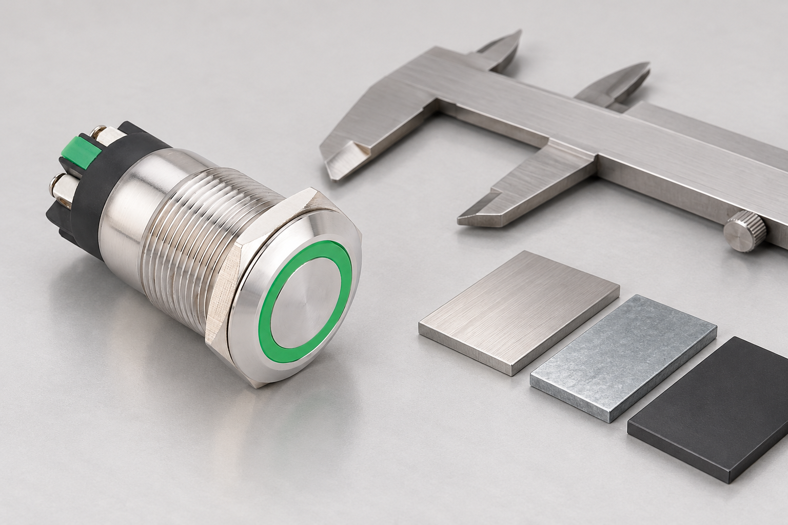
Define the finished mounting stack
Measure the surfaces that the mounting arrangement actually captures. Depending on the approved design, these may include the structural panel, a front overlay, a legend plate, a gasket or a rear accessory. Specify assembly order because moving a washer or seal can change both fit and sealing. Do not add every nearby component blindly; determine whether each component is inside the clamped stack.
Use finished dimensions rather than raw material thickness alone. Paint, powder coating, laminated overlays and adhesive layers can affect seating and tolerance. A removable protective film should not silently become part of the released assembly. Document whether it remains during installation and whether its removal changes the joint. Qualify the real production stack rather than a bare-sheet prototype.
General joint principles are discussed in the NASA Fastener Design Manual, including grip, washers and fastening arrangements. Those principles help frame the review, but NASA fastener examples do not establish the allowable panel thickness or thread engagement for an ONPOW switch.
Evaluate tolerances instead of approving one sample
A successful trial with one panel and one switch does not cover every allowed production dimension. Compare the panel’s thickness tolerance, coating variation and accessory dimensions with the manufacturer’s permitted installation range. Review the thinnest and thickest intended finished stacks. The responsible designer should determine which combinations need representative assembly checks.
Use the drawing’s defined measurement surfaces. A caliper measurement across a curved flange or compressible seal may not represent the clamped thickness. Record the instrument and method when a small margin matters. If the panel bows or the coating is uneven around the hole, resolve that surface condition before treating the measured thickness as the only variable.
A nominally acceptable stack may still be unsuitable if the nut bottoms out elsewhere or a locating feature fails to engage. Inspect seating, retention and operator movement in addition to dimensions. Where the product has specified acceptance criteria, use those criteria. Do not invent a minimum number of visible threads as a universal release rule.
Use a stack review table
This table identifies checks to include in a design review. It is not a substitute for the manufacturer’s dimensional limits. Add the approved drawing reference and actual measured or specified dimensions to the project record.
| Stack element | What to establish | Common review mistake |
|---|---|---|
| Structural panel | Material, finished thickness and local flatness | Using the nominal sheet thickness without tolerance |
| Coating or overlay | Whether it is captured and remains in service | Qualifying bare metal while production uses an overlay |
| Front seal | Correct part, position and approved assembly condition | Adding a second seal to compensate for a loose fit |
| Legend plate | Compatibility with the operator and mounting stack | Assuming a plate adds no meaningful thickness |
| Retaining hardware | Correct nut or clip and its approved position | Replacing supplied hardware with a visually similar part |
| Rear accessory | Whether it occupies clamping space or only cabinet space | Confusing stack thickness with rear clearance |
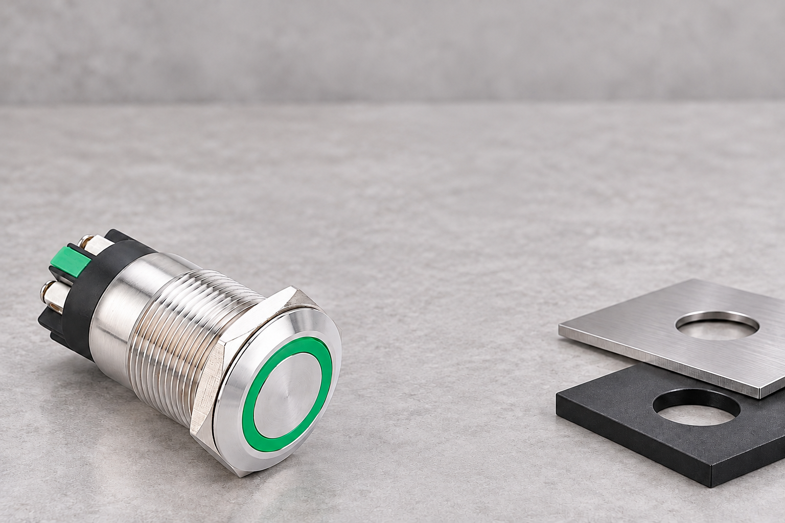
Preserve sealing when changing the stack
Adding a legend plate, changing a panel material or introducing a textured finish can change the sealing interface. A switch’s published protection rating applies under defined conditions; it does not automatically qualify every custom panel arrangement. Verify the gasket contact surface, assembly order and the exact environmental boundary before claiming that the completed enclosure meets an exposure requirement.
Do not sand a gasket, remove a washer or crush a soft panel to make the nut fit. These changes can hide a dimensional mismatch while creating a different installation. If a layered panel is essential, ask for a compatible operator or an approved mechanical redesign. Recheck the whole assembly after the design change rather than retaining the original qualification statement.
The HSE electrical safety introduction explains general duties around suitable and safely maintained electrical equipment. Its guidance supports a competent installation process; it does not certify a particular panel stack. For the related product boundary, see the IP65 versus IP67 sealing guide.
Handle thin and thick panels as different design problems
A thin panel may flex around the operator under repeated use or during tightening. Correct nominal thickness does not establish sufficient local stiffness. Review the panel geometry, nearby openings and support arrangement. Any proposed reinforcement should be engineered and checked for compatibility with the switch mounting and seal rather than introduced as an undocumented shop-floor spacer.
A thick panel may consume the available clamping range or obstruct accessory engagement. A counterbore, recess or alternate operator may be possible, but each changes the design and requires review of strength, edge condition, sealing and access. Do not machine a recess into a finished enclosure simply because a nut cannot start. Resolve the mismatch before releasing drawings and purchase orders.
Both cases require an operation check after assembly. The front flange should seat as intended, the operator should move freely, and the retaining system should meet its documented inspection criteria. Keep the circuit isolated during mechanical work and follow the site’s procedure when removing a device from existing equipment.
Prepare a useful supplier request and acceptance record
Send the supplier the intended product code, panel material, finished thickness range, cutout drawing, coating, accessories and environmental requirements. Ask for the applicable mounting range, installation method and any restrictions on legend plates or overlays. State whether the operator must be removable from the front or whether maintenance has rear access. These details can prevent a late redesign.
In the acceptance record, identify the drawing revision, stack components, representative assembly conditions and inspection results. Include photographs of the seated flange and retaining hardware, but retain the dimensional evidence separately. A photograph can show assembly order; it rarely establishes a small tolerance or a hidden contact surface reliably.
Gunakan push button panel design guide to coordinate neighboring controls and service access. When the assembly changes, revisit the thickness, cutout and rear-clearance checks together. This keeps a successful replacement from creating a new mechanical or wiring problem elsewhere in the panel.
Pertanyaan yang sering diajukan
Does a 22 mm cutout specify the permitted panel thickness?
No. The cutout describes a mounting opening. Allowable panel thickness depends on the selected model’s retaining system and approved hardware stack. Obtain both requirements from the current drawing.
Can I calculate the maximum thickness from the exposed threads?
Visible threads alone are insufficient. The retaining nut, seating surfaces, gasket and required engagement all matter. Use the manufacturer’s approved mounting range rather than estimating from a product photograph.
Does a legend plate count toward panel thickness?
It can when it is captured in the mounting stack. Confirm the approved plate and assembly order with the manufacturer. Recheck the finished stack and seal whenever an accessory is added.
What should I do if the panel is outside the approved range?
Select a compatible operator or obtain an approved panel redesign. Do not remove seals, substitute retaining hardware or force the assembly to fit without reviewing the changed mechanical and environmental conditions.
Further learning
NPTEL university lecture on dimensional measuring instruments. It complements the panel stack measurement review; product-specific mounting limits still come from the approved switch drawing.
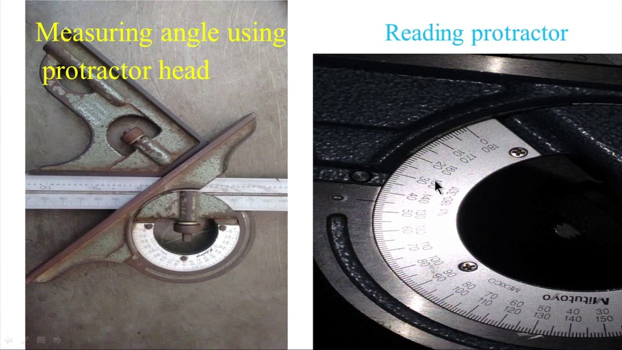
Linear measuring instruments – 2 (Combination set, Vernier calipers) — nptelhrd



