

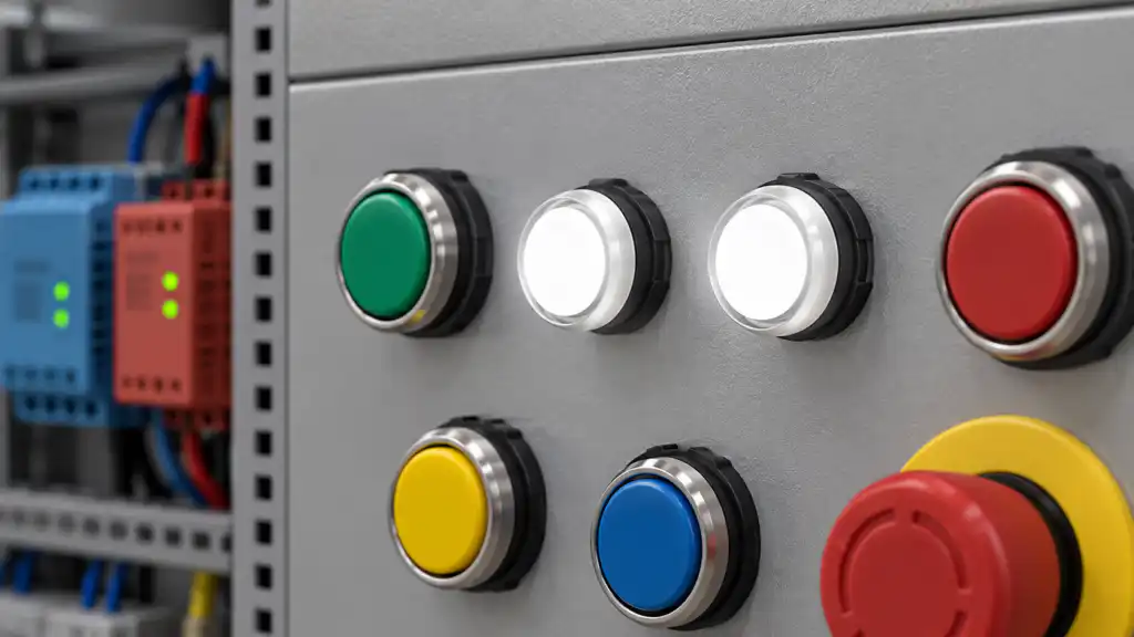
Choosing between a 12V and 24V LED indicator light starts with the actual supply at the panel terminals—not with the nominal voltage printed on a machine specification. A 12V circuit can sit above or below its nominal value, and a 24V control supply can have tolerance, ripple, switching transients, and a different reference to protective earth. The indicator’s exact AC/DC input range, polarity, current, cutout, lens, brightness, and environment must all match the circuit. An indicator rated for the wrong voltage can fail early, glow dimly, or create a misleading machine-status signal.
What the voltage rating means
The rating describes the electrical input the lamp module is designed to receive. It is not the voltage that a nearby PLC, relay coil, or power supply happens to provide. Read the complete marking and datasheet: a part may be specified for 12V DC, 24V DC, 12–24V DC, 110–240V AC, or a different range entirely. AC and DC are not interchangeable just because their nominal numbers look similar.
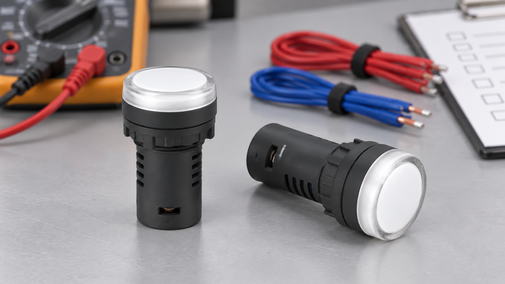
その ONPOW AD16-22D product page shows the physical form of a panel signal lamp. The product photograph is useful for matching the body, bezel, and lens, but the exact electrical variant must still be selected from current product documentation and the order code. Do not use the photograph to infer a 12V or 24V rating.
Measure the real panel supply
Before selecting the lamp, measure the supply where the indicator will be connected. Check the normal value, minimum and maximum under load, start-up behavior, ripple, and what happens when the control transformer or DC supply is switched. If the panel uses a nominal 24V DC bus, the measured value can be higher at light load and lower when long cable runs or several coils operate.
Record the source, fuse or breaker, polarity, return conductor, and whether the circuit is SELV/PELV or part of another control architecture. If the indicator is connected to a PLC output, use the PLC’s voltage and current limits rather than the power supply nameplate alone.
12V versus 24V selection table
| Decision point | 12V indicator | 24V indicator | Evidence to record |
|---|---|---|---|
| Nominal supply | A 12V control or battery system | A 24V industrial control bus | Measured voltage at the lamp terminals |
| Wiring drop | A given drop is a larger percentage of the supply | The same drop is a smaller percentage | Cable length, conductor size, load current |
| PLC output | Must stay within output voltage and current limits | Must stay within output voltage and current limits | PLC datasheet and output test |
| 保護 | Fuse and transient protection sized for the 12V circuit | Fuse and transient protection sized for the 24V circuit | Schematic and panel test |
| Variant risk | Wrong 24V part may remain dim or fail to illuminate | Wrong 12V part may be overdriven | Exact part marking and datasheet |
| Field replacement | Stock the exact 12V variant | Stock the exact 24V variant | Approved spare list and label |
This is a selection framework, not a claim that every ONPOW lamp is available in both voltages. The current model, lens color, illumination type, and supply variant must be confirmed together.
Why a wrong voltage causes misleading signals
An under-voltage LED module may glow weakly, change apparent color, or fail to meet the visibility requirement. An over-voltage module may draw excessive current, heat its internal components, or fail immediately. A lamp that is technically lit can still be unsuitable if glare, ambient light, viewing angle, or lens color makes the status ambiguous.
For a machine status indication, define what “on” means and what a failed lamp means. A pilot light is normally an indication path, not proof that a motor, valve, heater, or safety function has completed its action. Where the state is important, use feedback from the controlled device and treat the lamp as a human-facing display.
AC, DC, polarity, and shared returns
Confirm whether the indicator accepts AC, DC, or both. A DC-only lamp may require polarity; reversing the leads can prevent illumination or damage the device. A shared 0V return can create unintended current paths when multiple lamps, sensors, or PLC outputs are combined. Draw the return path and check it during commissioning.
If the circuit is switched on the low side, the lamp’s positive terminal may remain at the supply while the controller switches the return. If it is switched on the high side, the return may be fixed and the output supplies the positive side. This distinction matters for measurement and troubleshooting, but it does not change the need to match the indicator’s exact rating.
Brightness, lens, and human factors
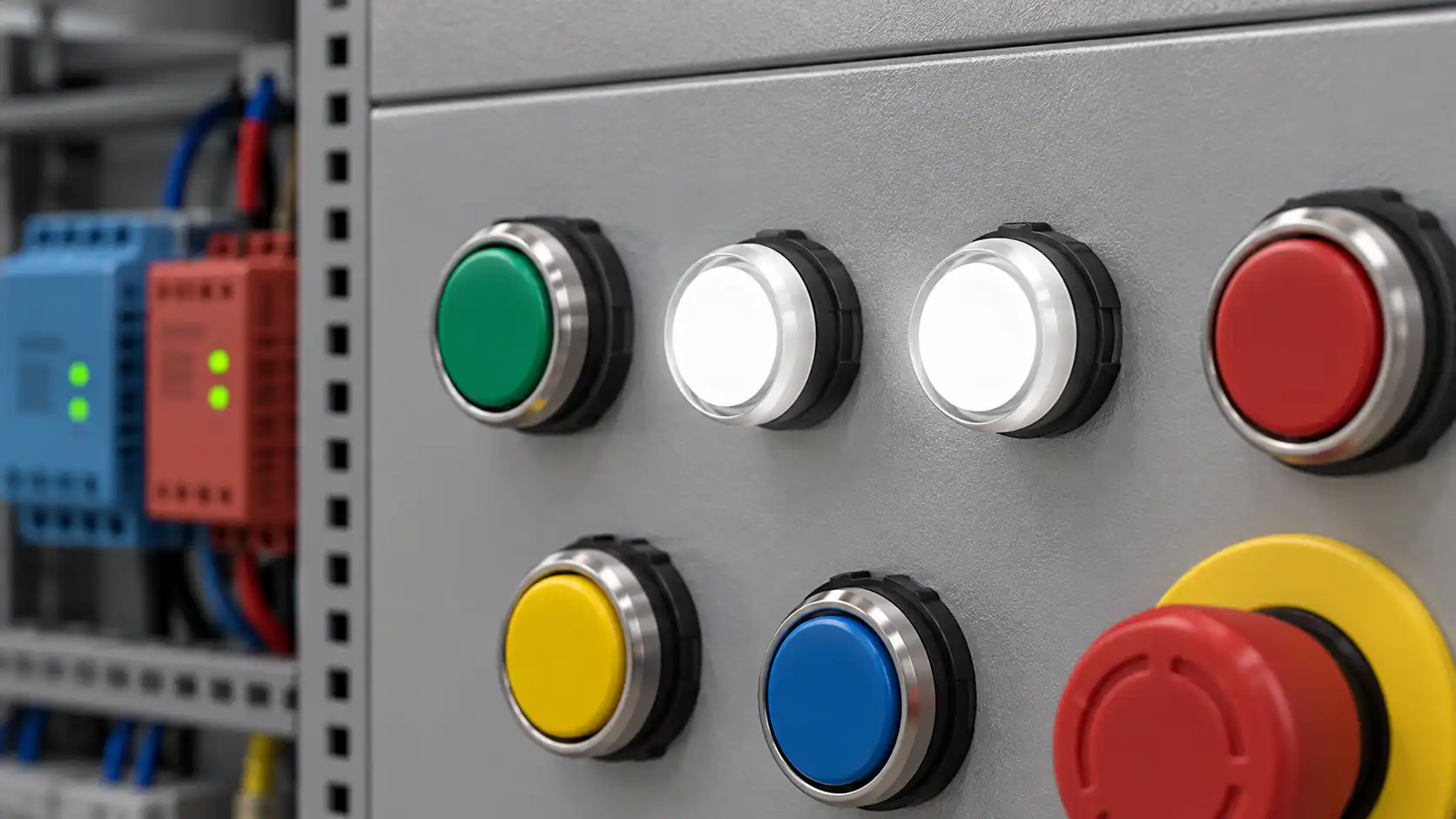
Voltage is only one part of a visible signal. Choose lens color and intensity for the viewing distance, ambient light, panel angle, and machine status convention. A white lens may be used for general indication, while red, green, amber, or blue can carry defined meanings in a project standard. Do not change colors casually during replacement; a different color can change the operator’s interpretation.
Avoid placing an indicator where a nearby illuminated push button creates reflections or overwhelms the lamp. Use a consistent spacing and label system. The ONPOW indicator-light selection guide provides broader guidance on application and equipment context, while the control-panel layout guide helps coordinate buttons and indicators.
Wiring and protection checks
Use the manufacturer’s terminal and wire-range instructions. Protect the branch circuit according to the panel design, and do not assume that a small indicator can be connected behind any fuse simply because its steady current is low. Inrush, shared loads, and short-circuit protection still matter.
Keep low-voltage control wiring separated from higher-energy conductors as required by the applicable installation rules. Provide strain relief at door-mounted devices and leave enough service length for maintenance. Verify torque, strip length, ferrule size, and enclosure sealing from the exact product drawing.
For LED loads controlled by solid-state outputs, check leakage current and minimum load requirements. A lamp that faintly glows when “off” may be responding to output leakage or an incorrect return path. Solve the circuit cause rather than masking the symptom with an unverified resistor.
Commissioning a replacement indicator
- Isolate the circuit using the approved electrical safety procedure; the indicator itself is not an energy-isolating device.
- Compare the delivered model, lens, terminals, voltage, frequency, and polarity with the approved bill of materials.
- Measure the supply at the lamp terminals before connecting the new part.
- Check continuity and insulation according to the panel test plan.
- Energize under controlled conditions and verify brightness, color, viewing angle, and off-state leakage.
- Trigger the real machine condition and confirm that the lamp tracks the intended feedback or command.
- Record the result, part number, date, test instrument, measured voltage, and approver.

If a replacement does not illuminate, check polarity, output type, common return, fuse status, and the exact voltage variant before assuming the lamp is defective. If it illuminates dimly, measure voltage under load and check for leakage or an incorrect series component. Never substitute a 12V lamp into a 24V circuit as a diagnostic experiment.
Environment and enclosure considerations
Indoor control-panel use still involves dust, condensation, vibration, heat, cleaning, and door movement. Specify the required front protection and installation method from the product datasheet and the complete enclosure design. “Waterproof” or an IP statement for a front component does not describe every cable entry, rear terminal, door gasket, or enclosure seam.
Temperature affects LED output, power-supply behavior, and material life. Check the operating range and derating information for the chosen variant. If the panel is washed down or exposed to chemicals, confirm compatibility and test the assembled enclosure; do not equate an indoor rating with an outdoor installation or the reverse.
選択に関するよくある間違い
Choosing by nominal voltage only
Two supplies both called 24V can have different tolerances, ripple, and grounding. Measure the actual circuit and read the input range.
Mixing AC and DC variants
The number “24” does not identify waveform, polarity, or internal circuitry. Match AC/DC type and frequency where applicable.
Treating a lit lamp as machine feedback
The lamp reports the electrical path that drives it. It does not prove that the downstream load moved, closed, or reached a safe state.
Replacing lens color without approval
Color is part of the operator interface. A visually convenient replacement may create a new interpretation risk.
Ignoring the rear connection
The front bezel and lens can match while the terminal system or body depth differs. Check panel thickness, rear clearance, and wire routing.
RFQ checklist for 12V or 24V indicators
Send the supplier:
- measured nominal, minimum, and maximum voltage at the installation point;
- AC or DC waveform, frequency, polarity, and return arrangement;
- PLC/output module type and allowable current or leakage;
- lens color, brightness, viewing distance, and status convention;
- panel cutout, thickness, front protection, temperature, vibration, and cleaning conditions;
- terminal style, wire range, accessories, and rear clearance;
- required documents, markings, samples, spare-part identification, and acceptance test.
その ONPOW signal-lamp range and the AD16-22D product page are starting points for matching the physical lamp family. Confirm the exact voltage variant with ONPOW through the contact page before issuing a purchase order.
教育ビデオ
This neutral Electronics For You demonstration concerns a 12V/24V voltage-indicator circuit. It is background on comparing voltage levels, not a substitute for the ONPOW indicator’s current datasheet or wiring instructions.
よくある質問
Can a 12V LED indicator run on 24V?
Only when the exact product documentation explicitly allows that input range. Do not infer dual-voltage capability from the lens or body appearance.
Is 24V always better for an industrial panel?
No. It may reduce the percentage impact of wiring drop, but the panel supply, controller, load, protection, and approved standard determine the correct choice.
Why does an LED indicator glow when off?
Possible causes include solid-state output leakage, a shared return, induced voltage, or incorrect wiring. Measure the circuit and compare it with the output module and lamp requirements.
Does an IP rating prove the complete indicator installation is waterproof?
No. The rating applies to a defined product configuration and test boundary. The panel cutout, gasket, rear wiring, and enclosure must also be designed and verified.
最終決定
Choose 12V or 24V only after measuring the real panel supply and matching the exact indicator variant, waveform, polarity, current behavior, lens, and environment. Verify the installed lamp under the actual machine condition, record the result, and keep the approved part number visible in the spare-parts system.
Sources for verification: ONPOW AD16-22D product page; IEC 60947-5-1 制御回路機器; IEC 60529 enclosure protection classifications; Electronics For You 24V/12V voltage-level indicator demonstration.
Customization
ONPOW undertakes a variety of custom needs for push-button development. Confirm whether packaging, marking or documentation OEM/ODM applies to 12V vs 24V LED Indicator Lights for Control Panels in the quotation.
Minimum order quantity, lead time and trade terms are not published here; confirm them with sales at sales@onpow.com.



