

A panel-mount USB connector brings a machine’s approved service interface to the enclosure surface, allowing a technician to connect without reaching the internal equipment port. Select it by connector arrangement, supported data path, cable length, mounting geometry and the environmental conditions of the complete installation. A familiar USB socket does not prove a particular data speed, charging capability or sealed condition. Define the maintenance task first, then qualify the connector, internal cable, external cable and host together. Keep access permissions and enclosure requirements in the same design review as the physical port.
Decide what the service port is for
Write a short use case before selecting hardware. The port might transfer a recipe file, connect a diagnostic device or provide an approved maintenance connection. Each task has different consequences if a user connects an unintended device. Identify who may use the port, when the machine may be connected and what equipment is permitted.
Determine whether the interface must remain externally available during normal operation. A frequently used service connection may justify a clearly identified external socket, while an occasional commissioning connection may belong behind controlled access. Do not add an exposed port simply because a convenient spare panel hole is available.
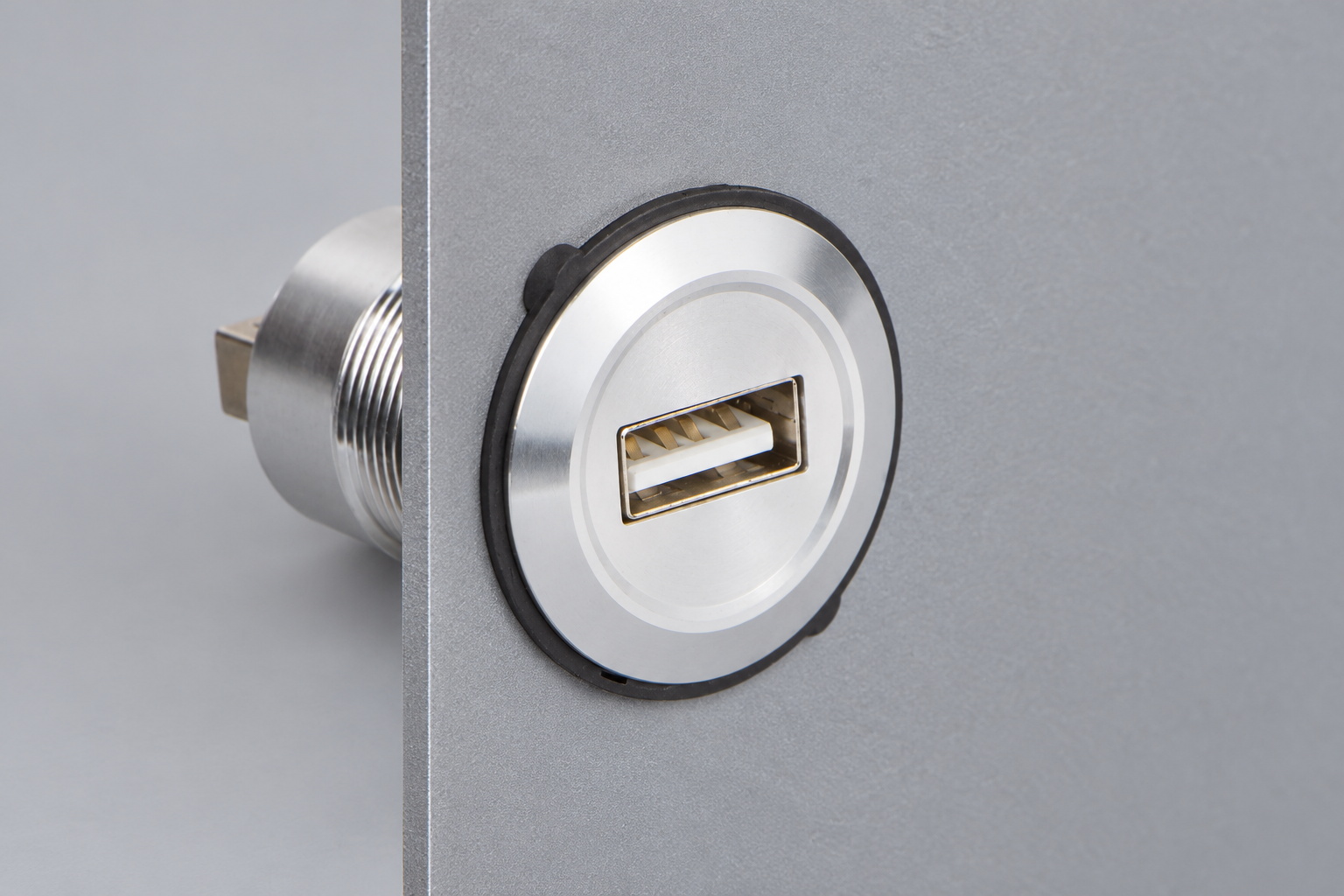
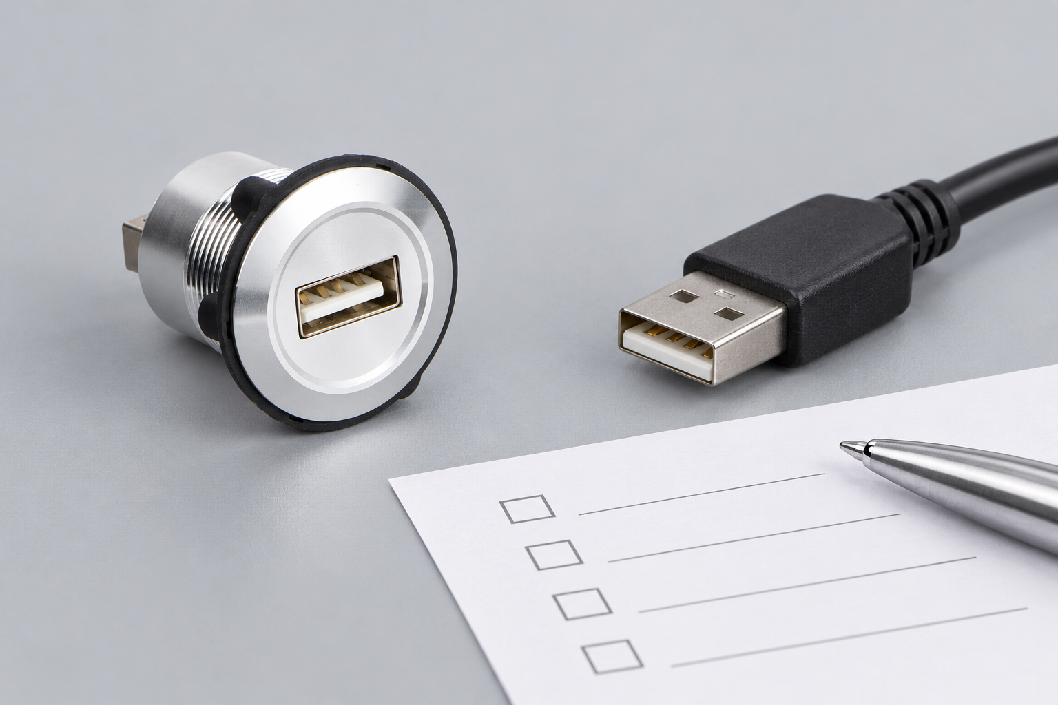
その ONPOW USB-01-(BK) product page provides a real panel-connector reference and drawing. Use the exact ordered version’s documentation to confirm its interfaces and mounting details. The product photograph illustrates the connector form; it does not independently establish protocol, environmental or certification claims.
Map the complete connection from host to device
Draw the host port, internal connection, panel adapter, external cable and intended peripheral. Identify the connector at both ends of every segment, including plug or receptacle gender. A front USB-A receptacle tells you little about the rear arrangement unless the drawing specifies it.
Keep host and peripheral roles clear. A mechanical adapter does not automatically create a host controller or convert one protocol into another. If the intended equipment requires active electronics, identify that requirement before choosing a passive panel feedthrough. Avoid building a chain of adapters merely to make connectors physically mate.
その USB-IF document library is the primary reference point for USB specifications and compliance material. Consult the applicable specification and equipment documentation for the actual design. A catalogue phrase such as “USB connector” should be followed by a precise statement of supported functionality.
Separate connector appearance from data capability
A connector’s shape and its data performance are different characteristics. Confirm the complete assembly’s supported connection, including internal wiring and any extension cable. A socket that accepts the intended plug may still limit or interrupt the required function. Use supplier documentation and a representative end-to-end test rather than relying on colour or appearance.
Describe the required task in measurable terms. For a file-transfer interface, specify the actual device and representative files. For a diagnostic connection, identify the tool and software version. The acceptance test should reproduce what maintenance staff must accomplish, not merely prove that the operating system notices something connected.
If several equipment variants share one panel design, identify which interface is fitted in each variant. An unused or differently wired socket can confuse technicians. Keep the interface label, internal harness and software configuration aligned with the machine’s documented service procedure.
Use a selection table before ordering
The following qualitative checklist defines questions for the exact assembly. It does not assign a data speed, ingress rating or current capability to the referenced ONPOW connector.
| Selection item | What to confirm | Evidence to retain |
|---|---|---|
| Maintenance function | Approved host, peripheral and task | Service use case and equipment manuals |
| Front and rear interface | Connector types, gender and cable arrangement | Configuration-specific drawing |
| Data path | Required function through the complete assembly | Supplier declaration and end-to-end test |
| Power path | Permitted source, load and cable capability | Equipment and assembly specifications |
| マウント | Cutout, panel thickness and rear clearance | Approved mechanical drawing |
| 環境 | Open, capped and connected conditions | Exact applicable assembly evidence |
| Access control | Authorised users and devices | Site maintenance and security procedure |
Plan the panel opening and rear space
Use the actual drawing to define the cutout and mounting stack. Include panel thickness, coating, gasket, retaining hardware and any anti-rotation feature. Do not scale a website photograph to estimate a hole dimension. Confirm that the supplied hardware works with the finished panel rather than only a thin prototype coupon.
Reserve space behind the connector for the internal cable and its required bend. A connector that fits through the panel may still leave insufficient clearance for a plug, strain relief or maintenance access. Check the door swing and nearby equipment before freezing the layout. Keep the cable away from sharp edges and moving hardware.
The general control panel layout guide covers the wider arrangement. A service port should be reachable without obscuring commands or inviting accidental contact with an operator. Plan labels and cap access at the same time as the hole positions.
Review sealing in each operating condition
Ask what the environmental statement covers: the connector front, a fitted cap, a mated connector pair or a complete enclosure installation. These conditions are not automatically equivalent. The rear of a panel connector may remain exposed inside the cabinet even when its front mounting interface is sealed.
その IEC 60529 publication page identifies the ingress-protection classification framework. It does not establish an IP rating for an arbitrary connector assembly. Request the exact evidence and installation conditions for the product being ordered, then assess the complete enclosure.
Define how maintenance staff restore the protected condition after use. A cap left open changes the installation state. Consider tethering, storage, cleaning and inspection only where the selected product supports those arrangements. Do not improvise sealants or cleaning chemicals that the manufacturer has not approved.
Qualify data and power as separate functions
A successful data connection does not prove a power capability, and a device that receives power may still lack the required data path. Check both against the intended task. Do not use a charging result as evidence that a diagnostic application will operate correctly through the panel assembly.
Test the complete cable arrangement at its intended length, with the actual host and peripheral. Record the cables, adapters, equipment and software used. A short bench lead may produce a different result from the final cabinet route. If the design changes later, identify which qualification checks need to be repeated.
For another panel-interface context, review push button connector assemblies, while keeping data connectors separate from switch harness connectors. Reversible connector shape introduces its own role and orientation questions; it should not be treated as a cosmetic replacement for a legacy USB socket.
Include maintenance access and cybersecurity
An external service port can make maintenance more convenient while also creating an access point. The equipment owner should define permitted devices, software and file-handling procedures. The connector itself does not enforce those rules. Coordinate the physical port with the controller or industrial computer’s security configuration. Compare this interface with snap-in push button connector sockets: those sockets simplify switch wiring, whereas a USB service port carries an equipment data interface.
Keep the interface purpose visible and precise. A label such as “service USB — authorised maintenance only” may be appropriate where it accurately describes the approved use. Avoid suggesting that the port is a general charging outlet when it is connected to control equipment. The final wording should follow the machine’s documentation and local language needs.
NIST SP 800-82 discusses operational-technology security. Use it as broader system guidance rather than a connector certification. The practical design decision is to make the approved maintenance path clear and controlled, with responsibility assigned to the equipment owner.
Build a realistic acceptance test
Mount the connector in a representative finished panel and route the actual internal harness. Check plug insertion, removal, cap operation where fitted and access with the intended tools. Verify that normal service handling does not pull on the internal host connector or damage adjacent wiring.
Perform the approved maintenance task repeatedly under representative operating conditions. Record disconnects, error messages, transfer failures and recovery behaviour. A port that works only after opening the cabinet and rearranging the cable has not demonstrated the intended service-access benefit. Keep failures traceable to the exact assembly and cable set.
Before production release, save the drawing revision, supplier code, internal cable identity, external cable requirements and acceptance result. Maintenance staff should be able to replace the assembly without guessing its data function from the front socket alone. Contact ONPOW with the complete connection diagram and mounting constraints to confirm the appropriate configuration.
よくある質問
Is a panel USB connector automatically an active hub?
No. Determine whether the selected assembly is passive or includes electronics. A feedthrough does not automatically add host capability or protocol conversion.
Can a metal mounting body prove an ingress rating?
No. Ask for evidence covering the exact product, mounting arrangement and open, capped or connected condition involved.
Does a charging test prove that data transfer works?
No. Power and data are separate acceptance questions. Test the actual maintenance function with the intended equipment and complete cable path.
What should be included in a quotation request?
Provide the host and device interfaces, required task, data and power requirements, cable arrangement, panel drawing, environmental conditions and access-control needs.
Further learning
University background on USB storage and host/device communication for understanding a service data path. It is not a connector qualification or current product specification.



