

Push button cable strain relief should transfer cable movement and pulling forces into suitable supports rather than the switch terminals. Start with the installed cable route, especially where a control-panel door moves, then select supports compatible with the cable and enclosure. A tight terminal screw, ferrule or mating connector does not replace mechanical cable support. This guide explains how to document the load path, review a moving cable loop and qualify the finished assembly without inventing a universal pull force, bend radius or clamp spacing. Work on equipment only through the machine’s approved isolation and maintenance procedure.
Define what the cable support must protect
A panel-mounted button creates several different interfaces: the head and panel, the rear terminals, the individual conductors, the outer cable jacket and any enclosure entry. These interfaces do different jobs. The retaining nut holds the button in the panel. A terminal establishes the specified electrical connection. A separate support can control where cable movement goes. None should silently inherit another component’s function.
For example, a neatly terminated cable may still hang from the rear of a door-mounted button. When someone opens the door, its weight or tension can act on the terminals. The first design question is where that load should be taken. Answer it with a drawing or installed-route photograph, rather than simply adding another cable tie wherever space remains.
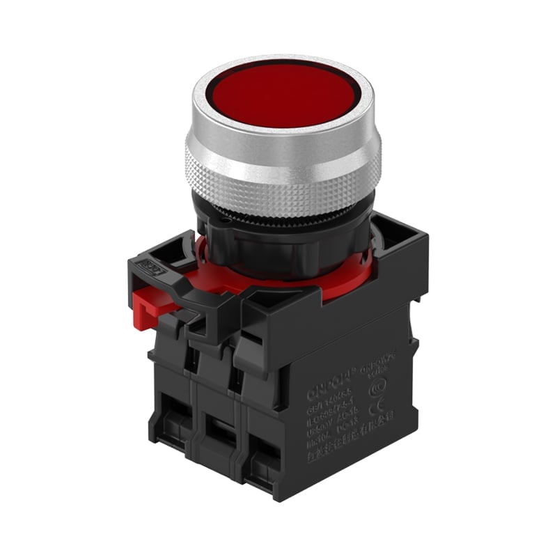
その ONPOW screw-terminal metal push button illustrates why the rear assembly needs its own review. Its product appearance identifies a terminal style; it does not establish a cable-clamp approval, conductor capacity or permitted pulling force. Obtain the exact assembly instructions for the ordered configuration before specifying termination and support hardware.
Map the load path before choosing hardware
Trace the cable from the enclosure entry to the button. Identify fixed sections, moving sections, connector locations and the point where the outer jacket ends. Mark where pulling, door movement, vibration or service handling could reach the individual conductors. A support attached beyond the jacket transition may leave the vulnerable section unprotected.
The desired load path should be deliberate. External cable forces should be handled by an entry or retention arrangement designed for that service. Inside the enclosure, supports should maintain the route without crushing insulation or forcing sharp turns. Where a door moves, the cable must accommodate the full approved travel without using terminal movement as the flexible joint.
NASA’s cable and harness workmanship standard addresses interconnecting cable and harness assemblies in its own application scope. It is useful background for separating workmanship and stress-control questions, but it is not an ONPOW product instruction or a general machinery requirement. Have the responsible equipment designer identify the standards and retention requirements that govern the actual installation.
Review the moving door loop as an installed assembly
A door loop needs room to move through its intended path. A cable that looks relaxed with the door closed may become taut near the maximum opening, or fold against an edge during closing. Inspect the route in both positions and through the intermediate movement, with the equipment in the safe condition required by the maintenance procedure.
Check both ends of the moving section. If only one end is supported, the other may transfer motion into the button terminals. Supports should guide movement to the intended flexible section, while preserving the cable manufacturer’s bend-radius and flexing conditions. A static-installation cable is not automatically suitable for repeated door movement merely because it can bend once during assembly.
Avoid a universal loop length. The required geometry depends on the hinge, support positions, door travel, cable construction and nearby obstacles. Record the approved routing with a clear photograph or drawing. If the cable is replaced with a different construction or outside diameter, repeat the route review instead of assuming that the old loop remains suitable.
Use a route-based inspection table
The table below is a qualitative design and inspection aid. Numerical limits must come from the approved cable, support, enclosure and equipment documentation. It is not a substitute for an applicable machinery standard or a specified retention test.
| 配置場所 | What to inspect | Evidence needed | Hold condition |
|---|---|---|---|
| Cable entry | Jacket retention and protection at the opening | Approved entry hardware and cable range | Cable moves against an unprotected edge |
| Fixed internal route | Support stability and insulation condition | Drawing and support instructions | Cable hangs from button terminals |
| Jacket transition | Individual conductors have controlled routing | Harness drawing and termination requirements | Pull reaches stripped conductors |
| Door loop | Full travel without tension, pinching or rubbing | Approved travel and cable flex requirements | Loop tightens before the door reaches its limit |
| cURL Too many subrequests by single Worker invocation. To configure this limit, refer to https://developers.cloudflare.com/workers/wrangler/configuration/#limits | cURL Too many subrequests by single Worker invocation. To configure this limit, refer to https://developers.cloudflare.com/workers/wrangler/configuration/#limits | cURL Too many subrequests by single Worker invocation. To configure this limit, refer to https://developers.cloudflare.com/workers/wrangler/configuration/#limits | cURL Too many subrequests by single Worker invocation. To configure this limit, refer to https://developers.cloudflare.com/workers/wrangler/configuration/#limits |
cURL Too many subrequests by single Worker invocation. To configure this limit, refer to https://developers.cloudflare.com/workers/wrangler/configuration/#limits.
Match the support to the cable and environment
cURL Too many subrequests by single Worker invocation. To configure this limit, refer to https://developers.cloudflare.com/workers/wrangler/configuration/#limits.
cURL Too many subrequests by single Worker invocation. To configure this limit, refer to https://developers.cloudflare.com/workers/wrangler/configuration/#limits.
cURL Too many subrequests by single Worker invocation. To configure this limit, refer to https://developers.cloudflare.com/workers/wrangler/configuration/#limits.
Keep termination quality separate from retention
cURL Too many subrequests by single Worker invocation. To configure this limit, refer to https://developers.cloudflare.com/workers/wrangler/configuration/#limits.
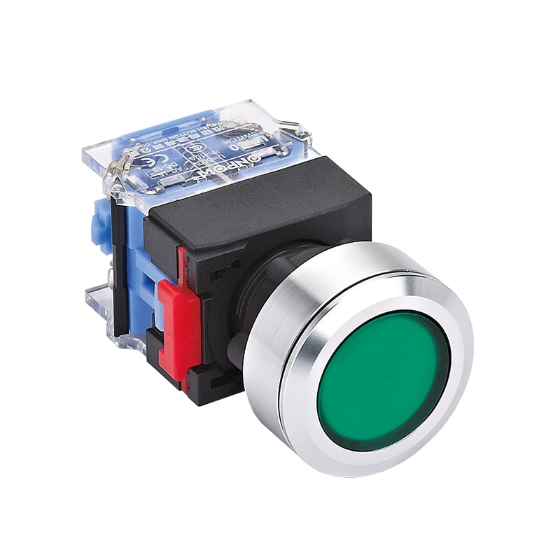
The guide to screw and solder push button terminals addresses the assembly-process choice. The separate ワイヤーフェルール互換性ガイド addresses conductor-end preparation. Neither establishes a clamp location or cable pull requirement. Keeping those decisions separate prevents a useful connection accessory from being mistaken for a complete cable-management solution.
If a connection style changes, review both the termination instructions and the available service space. A different terminal orientation can change the route even when the front operator and mounting hole are unchanged. Do not force the old harness around a new rear geometry.
Qualify movement and maintenance access
Define the inspection sequence before testing. Record the installed configuration, support identity, cable identity and permitted door travel. With the equipment safely isolated as required, inspect the cable through that travel and look for tension, pinching, contact with sharp edges and movement at the terminal entries. Do not perform improvised pulling on an installed safety-related control.
Any specified mechanical test needs an approved method and acceptance criteria. This article supplies no universal force or cycle count. A hand tug without defined conditions is not a documented retention qualification. If engineering requires a measured test, use the agreed fixture, loading direction, sample condition and disposition process, and retain the results with the harness revision.
Review service access too. A cable route should allow the authorized replacement sequence without using the conductors as handles. The mounting-depth guide helps identify the space behind the button, while this article focuses on where movement and load travel. Allowing physical depth alone does not prove that the cable can be disconnected and restored correctly.
Freeze the accepted route and manage changes
After acceptance, make the route repeatable. Include support locations, hardware references, cable identity and useful photographs in the assembly record. Describe how the loop should sit at the defined door positions. Clear records make inspection more consistent than instructions such as “leave enough slack,” which different assemblers may interpret differently.
Have maintenance record damaged supports, jacket wear and repeated conductor movement as evidence. Replacing the visible damaged part may be necessary, but investigate why it failed. A support that repeatedly releases can indicate unsuitable mounting conditions, unplanned door travel or a cable change. Resolve the cause before approving the same arrangement for more panels.
For an ONPOW application review, send the complete button code, rear-terminal photograph, cable data, door geometry and route drawing. Ask about the button’s connection requirements without assuming that ONPOW approves third-party support hardware. Use HSE’s electrical maintenance guidance when defining safe work arrangements; the equipment owner remains responsible for the actual maintenance procedure and release decision.
For the wider installation context, see the プッシュボタンパネル設計ガイド. Its layout and verification principles complement this article; the specific acceptance criteria still belong to the approved equipment documentation.
よくある質問
Does a tight terminal screw provide strain relief?
端子のねじをケーブルの支持手段として扱わないでください。端子の接続要件に従い、ケーブルの配線経路と機器の設計に応じて必要な固定構造を設けてください。電気的接触と機械的負荷の制御については、それぞれ別個に根拠を確認する必要があります。.
すべてのパネルケーブルに対して同じ曲げ半径を使用できますか?
No. Use the cable manufacturer's requirements for the actual construction and service, including repeated flexing where applicable. Review the complete installed movement rather than applying an unsupported general radius.
ケーブルタイは常に許容されるサポートですか?
No. Establish whether the exact tie, mounting base and fixing method are suitable for the required retention duty and environment. A part used to organize wires is not automatically approved to carry cable loads.
Should a replacement cable keep the old route?
Recheck it. Changes in stiffness, outside diameter, jacket material or flexing suitability can alter the moving loop and support requirements even when the conductors have the same electrical size.
さらに詳しく学ぶ
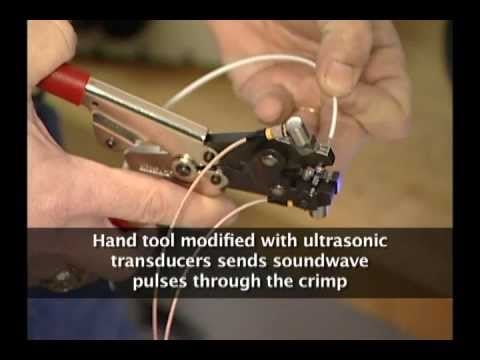
NASA educational demonstration of crimp tooling, accompanying the section that separates termination workmanship from cable retention. It does not approve this button, a clamp or a cable route.
NASA | Crimp Tool for Safe and Efficient Critical Wiring Needs — NASA Langley's Technology Gateway



