

セレクタースイッチの記号は、電気図面に示される制御機能を表しており、設置されたスイッチの完全な図ではありません。接点状態、動作機構、デバイスの参照、位置ラベル、および図面の規則を一緒に読み取ります。多位置セレクターの場合、接点表は各位置で開いているか閉じているかを最も明確に示す方法です。記号の外観だけで代替品や端子の割り当てを選択しないでください。承認された回路図、正確な製品の接点配置、および機械モードの要件が一致している必要があります。工業用セレクターを指定または配線する前に確認してください。.
記号と製品写真を区別する
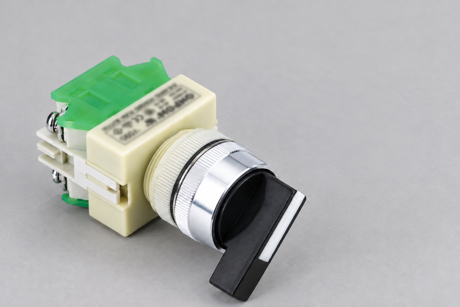
写真は可視のノブ、カラー、ハウジング、端子を示します。スキーマティック記号は機能的な関係を示します。配線図は接続情報を追加し、パネルレイアウトは物理的な配置を示します。これらの資料は異なる質問に答えるものであり、代替品として扱わないでください。.
一つの回転アクチュエータは複数の接点要素を操作できます。スキーマティックは、それらの接点を図面の異なる場所に示すことがあり、各回路を理解しやすくします。接点は同じ物理デバイスに属している場合でも、隣接して描かれていなくても構いません。デバイスの参照と図面に記録された機械的関係を使用して、その接続を確立してください。.
逆に、近くに描かれた二つの接点記号は自動的に同じアクチュエータを共有しているわけではありません。実際の識別情報と結合情報を確認してください。読みやすさのために選ばれたページレイアウトは、物理的な組み立て指示ではありません。.
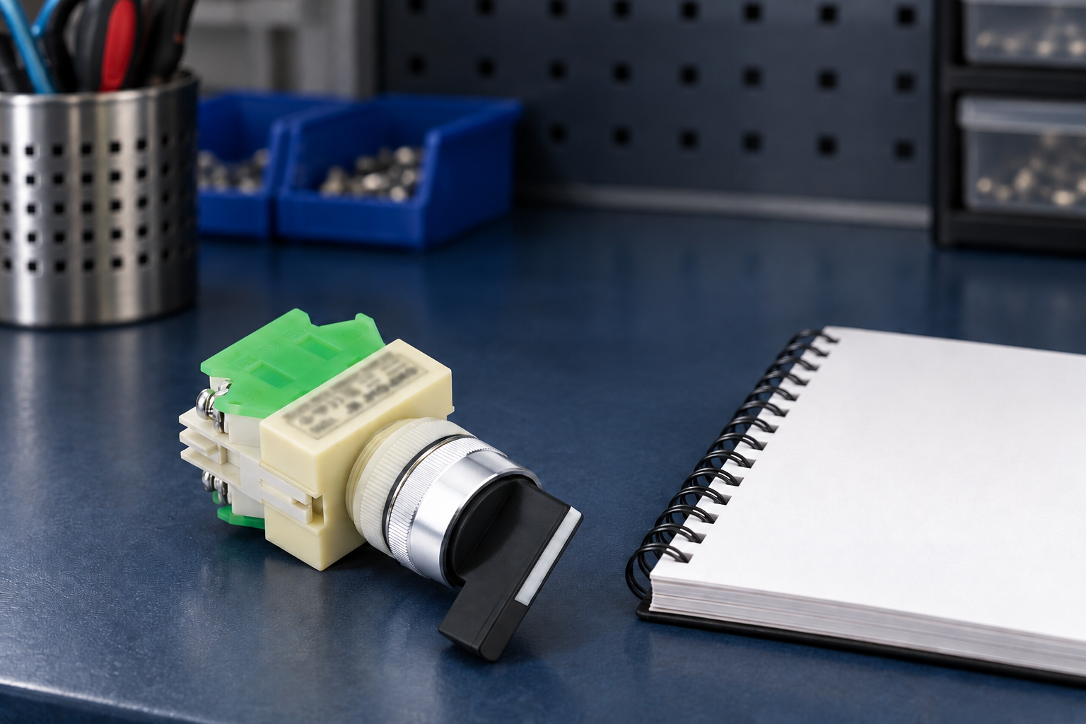
その ONPOW Y090セレクター組立 回転ヘッド、取り付けカラー、後部接点配置の実例を示します。その可視形態は製品ファミリーの識別に役立ちます。正確な供給注文コードと接点のドキュメントは、回路図にマッピングするために必要です。.
操作子と機構のより広い視野については、 セレクタースイッチタイプガイド. を参照してください。その選択コンテキストを使用して、選択したアセンブリを図面にマッピングします。.
適用される図面の規則を確認する
未知の図面を解釈する前に、タイトルブロック、凡例、改訂、適用される記号体系を確認してください。 IECグラフィカルシンボルによる回路図情報 IEC 60617を該当する回路図シンボルデータベースとして識別します。その役割は 機器に使用されるグラフィカルシンボルと混同しないでください, これらはシンボルの異なる使用目的に対応しています。.
すべての電気図面が同じ外観を使用しているとは限りません。機械メーカーは、用途特有の命名法、クロスリファレンス、状態規則も記録できます。シンボルが誤って描かれていると判断する前に、それらの注釈を読んでください。.
凡例や出典資料が欠落している場合は、検索結果の画像からシンボルの解釈を選択するのではなく、管理された図面を入手してください。無断のオンラインアイコンは、回路に重要な修飾語を省略している場合があります。このガイドは、情報を一緒に読む方法を説明するものであり、すべてのセレクターメカニズムに適用される未検証の普遍的アイコンを提供するものではありません。.
通常開と通常閉には定義された状態が必要です
開いているまたは閉じていると示された接点は、図面の指定された基準条件に対して意味があります。複数の位置を持つセレクターの場合、どの位置が表されているかを確認してください。「通常」や「オフ」という言葉は、実際の回路資料がその関係を確立していない限り、交換可能ではありません。.
保持式セレクターは、操作者が離れた位置に留めることができます。スプリングリターン式セレクターは、そのメカニズムによって指定された位置に戻ります。接点の状態は、その動作とともに解釈する必要があります。開いている接点のシンボルだけでは、操作者がノブを保持する必要があるか、位置が維持されているか、他の位置が何をするかを判断できません。.
端子番号や接点ブロックの左から右への外観だけで機能を割り当てることは避けてください。正確な端子図と記録されたビューを使用してください。背面図と正面図は、視覚的な左右を逆にし、接点の機能が正しく理解されていても配線エラーを引き起こす可能性があります。.
その 二位置セレクタ配線ガイド 特定のモード計画の文脈に対応します。このシンボル読解ガイドを補完しますが、すべての二位置製品の端子仕様として受け取らないでください。.
複数の位置には接点表を使用する
各セレクタ位置を列とし、関連する接点ペアを行とした表を作成または入手してください。実際のメーカーの規則に従って開閉状態を示してください。表は、単にノブの位置数ではなく、正確な製品構成を特定すべきです。.
ハンド、オフ、オートなどの位置ラベルは、意図された機械モードを示します。それだけでは、どの電気接点を閉じる必要があるかを確立しません。制御設計は、それらの動作要件を接点状態、コントローラー入力、コイル回路に変換します。動作要件と部品配置をリンクさせつつも、区別してください。.
三位置モード制御の場合は、補完的な ハンド–オフ–オート計画ガイド. を確認してください。別の目的で使用されるセレクターは、そのノブの位置数が同じでも、異なる表を必要とする場合があります。.
最終状態表から位置間の中間遷移を想定しないでください。重複または非重複の接点動作がアプリケーションにとって重要な場合は、関連するメーカー情報を入手し、設計レビューに含めてください。静的な回路図のスナップショットでは、その遷移動作を示さないことがあります。.
ドキュメント読取用の意思決定表
| 図面上の情報 | それが確立するのを助けること | 単独では確立できない内容 |
|---|---|---|
| 開いているまたは閉じていると描かれた接点 | 記録された基準条件における状態 | すべての状態のすべてのセレクタ位置 |
| アクチュエータまたはメカニズムの資格情報 | 正しく解釈されたときの意図された動作モード | 正確な商用注文コードと取り付け配置 |
| 一般的なデバイス参照 | どの分散接点がデバイスに属しているか | 製品図なしの物理端子位置 |
| 位置またはモードのラベル | 操作員向けの位置の目的 | 必要な接点シーケンスまたは安全な機械動作 |
| 接点表 | 識別された構成の接点状態 | Undocumented behavior during movement between positions |
| Terminal and wire identifiers | Actual circuit connections in the approved drawing | Permission to substitute a different contact assembly |
| Drawing revision and legend | Applicable interpretation and controlled reference | Whether the installed machine has been correctly modified |
The table describes a reading method. It deliberately does not assign a generic terminal combination, current rating, or contact sequence to an ONPOW selector.
回路を通じてセレクター信号を追跡する
After identifying a contact, trace what the circuit does when that contact changes state. It may feed a controller input, operate a relay circuit, or perform another documented function. The same-looking contact symbol can sit in different circuit contexts with different electrical requirements.
Keep physical contacts separate from software logic elements. A controller’s ladder-logic instruction can test a condition without representing a physical normally open contact in the field. Translate between the wiring drawing and program using the documented input mapping and logic, rather than assuming that matching graphic shapes are the same object.
Record the expected machine response for each mode and the conditions that can inhibit it. If selecting a mode does not produce the expected action, the selector may be functioning correctly while another permission is absent. Use the circuit and controller information to locate the actual boundary of the problem.
The following RealPars video explains conversion of a basic wiring diagram into a PLC program. It is supplementary education for the distinction between field devices and program logic, not a replacement for the machine’s approved drawing.

図面と物理的な組み立てを比較する
Compare the full actuator and contact-block order codes with the bill of materials and contact table. Check the release or return action, permitted positions, mounting details, and any relevant accessory. Similar external knobs can operate different contact arrangements.
Photograph the installed assembly and retain terminal identifiers before authorized disassembly. Establish the view used by the diagram. A photo taken from behind the panel can help preserve the physical relationship, but it does not validate an undocumented previous modification.
If the machine and drawing disagree, do not quietly redraw the diagram to match whatever is installed. Establish which change was authorized and obtain the controlled correction through the responsible engineering process. An apparently functioning circuit can still differ from the intended mode behavior.
最も一般的な記号読み取りの誤りを避ける
One mistake is treating a selector as a single contact simply because it has one knob. Another is treating every “Off” position as a hazardous-energy isolation function. A control selector can affect a command without disconnecting all relevant energy sources. For U.S. electrical work, 29 CFR 1910.333 provides relevant work-practice requirements; apply the actual servicing and isolation procedure.
Another error is counting positions without checking the contact table. “Three position” describes the actuator choices, while the actual contact arrangement describes the available electrical states. A replacement with the same position count can therefore fail the required circuit function.
A third error is ignoring the legend and revision. A copied image of a contact symbol may look familiar but omit a mechanism qualifier or reference-state note. Reading it outside the controlled drawing can remove precisely the information needed to interpret the selector correctly.
完全な証拠から交換問い合わせを準備する
Send the full existing order codes, approved schematic excerpt, contact table, mode labels, and photographs of the assembly and terminal arrangement. State whether each position is maintained or spring-return and whether transition behavior is relevant. Include the circuit interface and required documentation.
Ask the supplier to confirm the offered configuration against those requirements. Do not request a replacement merely by saying “the selector switch symbol looks like this.” A symbol provides functional information; purchasing needs a verified assembly identity and application context.
Keep the confirmed replacement identity with the updated controlled documentation and the machine’s acceptance record. After replacement, verify each required position and response under the approved procedure. A contact continuity check by itself does not demonstrate the complete machine behavior.
よくある質問
Is there one symbol for every selector switch?
すべての接点構成や操作機構を表す、例外のない単一のアイコンはありません。適用される記号規格、基準状態、機構、機器の識別情報、および位置表を併せて確認してください。.
ノーマリーオープン(常開)の記号で、実際の端子を特定できますか?
これは、記録された状態における接点機能を説明しています。実際の接続を識別するために、正確な製品端子図と承認された配線図を使用してください。.
Why are one selector’s contacts shown on different pages?
A schematic can distribute related contacts for circuit readability. Use common device references and documented cross-references to identify their shared actuator.
オフ位置は、メンテナンスのために機械を隔離しますか?
Do not assume that a mode-control position isolates hazardous energy. Follow the equipment’s approved isolation procedure and applicable workplace requirements.
接触テーブルと取り付けられたスイッチが異なる場合はどうしますか?
Verify the order code, drawing revision, terminal view, mechanism and authorized modifications. Resolve the discrepancy before accepting a replacement or changing the circuit.



