

A lighted toggle switch combines switching contacts with a lamp or LED, but the indicator may be internally connected, share a terminal, or use separate terminals. First determine whether the light should show power available, switch commanded, or load actually energized. Then use the exact lamp voltage and terminal diagram. This guide explains a safe identification and verification process for engineers, panel builders, maintenance teams and buyers. It does not replace the current datasheet, machine risk assessment or locally applicable electrical requirements. The method keeps each decision traceable during purchasing, assembly, commissioning and later service.
신속한 결정
핀 수가 아니라 기능부터 시작하십시오. 필요한 유지 및 순간 상태를 기록하고, 모든 접점과 램프 회로를 식별한 다음, 문서화된 정격을 실제 부하에 맞추십시오. 식별 작업 중에는 전원을 차단된 상태로 유지하십시오. 설치 후 전기적 상태와 기계 반응을 모두 테스트하십시오. 어플리케이션이 위험한 동작을 제어하는 경우, 범용 스위치를 완전한 안전 기능으로 취급하는 대신 필수 안전 아키텍처를 사용하십시오.
선택 및 배선 기준
| 결정 | 확인해야 할 사항 | 공학적 이유 |
|---|---|---|
| Indication meaning | Choose power, command or load feedback | A glowing handle can otherwise give a false impression of machine status. |
| Lamp supply | Match AC or DC voltage and polarity where applicable | LED modules may be polarity-sensitive and voltage-specific. |
| Internal connection | Check whether the lamp shares line, load or common | Shared terminals limit the available indication logic. |
| Separate lamp circuit | Use isolated lamp terminals when independent feedback is required | Independent wiring can show a PLC or auxiliary-contact state. |
| Leakage current | Check compatibility with electronic outputs and high-impedance circuits | Small leakage can cause faint glow or unexpected input behavior. |
| Contact load | Treat switch contacts and lamp circuit as separate ratings | The lamp voltage does not establish contact capacity. |
| Heat and space | Allow for illumination module depth and temperature | A lighted body may need more rear clearance than an unlighted version. |
| Test states | Verify lamp and contacts in every lever position and fault state | The visible indication must match the documented meaning. |
이 표는 의도적으로 정성적인 것입니다. 수치 등급, 토크, 도체 크기, 절연 거리, 내구성 및 환경 한계는 정확한 장치에 대한 승인된 문서와 완전한 장비 설계에서 가져와야 합니다. 유사해 보이는 스위치라도 다른 내부 연결을 사용할 수 있습니다.
배선하기 전에 접점 로직을 이해하세요
폴은 몇 개의 독립적인 공통 접점 경로가 함께 작동하는지를 나타냅니다. 스로는 각 공통 접점이 선택할 수 있는 고정 접점의 개수를 나타냅니다. 이러한 용어들은 레버 위치의 수, 위치가 유지되는지 또는 모멘터리인지, 전환 중에 접점이 겹치는지, 표시등이 어떻게 연결되는지를 나타내지 않습니다. 그러한 세부 사항에는 위치별 접점 표가 필요합니다.
상단에는 단자들을 배치하고 측면에는 액추에이터 위치들을 배치하여 매트릭스를 그리십시오. 현재 도면이나 독립된 측정값으로 지원되는 연결부만 표시하십시오. “액추에이터가 위를 향한 후면 단자 뷰”와 같은 명확한 보기 방향을 포함하십시오. 이 간단한 기록은 조립 중 또는 추후 정비 시 거울상 도면, 회전된 부품, 하네스 캐비티 번호가 혼동되는 것을 방지합니다.
Indication meaning
확인할 사항: Choose power, command or load feedback. A glowing handle can otherwise give a false impression of machine status. The engineering record should name the exact order code, drawing revision, supply, load and operating state used for the decision. Check the component in its installed orientation because panel thickness, wire routing, adjacent hardware and actuator access can change the result.
확인하는 방법: 현재 제조업체의 단자도와 독립된 도통 테스트를 비교하십시오. 작동 전, 모든 유지 위치에서, 그리고 모든 모멘터리 위치에서 해제된 후에 측정한 상태를 기록하십시오. 문서와 측정값이 일치하지 않으면 전원을 공급하기 전에 중단하고 불일치를 해결하십시오. 단자 위치, 금속 색상 또는 유사해 보이는 스위치의 도면을 바탕으로 단자 기능을 절대 추론하지 마십시오.
Lamp supply
확인할 사항: Match AC or DC voltage and polarity where applicable. LED modules may be polarity-sensitive and voltage-specific. The engineering record should name the exact order code, drawing revision, supply, load and operating state used for the decision. Check the component in its installed orientation because panel thickness, wire routing, adjacent hardware and actuator access can change the result.
확인하는 방법: 현재 제조업체의 단자도와 독립된 도통 테스트를 비교하십시오. 작동 전, 모든 유지 위치에서, 그리고 모든 모멘터리 위치에서 해제된 후에 측정한 상태를 기록하십시오. 문서와 측정값이 일치하지 않으면 전원을 공급하기 전에 중단하고 불일치를 해결하십시오. 단자 위치, 금속 색상 또는 유사해 보이는 스위치의 도면을 바탕으로 단자 기능을 절대 추론하지 마십시오.
Internal connection
확인할 사항: Check whether the lamp shares line, load or common. Shared terminals limit the available indication logic. The engineering record should name the exact order code, drawing revision, supply, load and operating state used for the decision. Check the component in its installed orientation because panel thickness, wire routing, adjacent hardware and actuator access can change the result.
확인하는 방법: 현재 제조업체의 단자도와 독립된 도통 테스트를 비교하십시오. 작동 전, 모든 유지 위치에서, 그리고 모든 모멘터리 위치에서 해제된 후에 측정한 상태를 기록하십시오. 문서와 측정값이 일치하지 않으면 전원을 공급하기 전에 중단하고 불일치를 해결하십시오. 단자 위치, 금속 색상 또는 유사해 보이는 스위치의 도면을 바탕으로 단자 기능을 절대 추론하지 마십시오.
Separate lamp circuit
확인할 사항: Use isolated lamp terminals when independent feedback is required. Independent wiring can show a PLC or auxiliary-contact state. The engineering record should name the exact order code, drawing revision, supply, load and operating state used for the decision. Check the component in its installed orientation because panel thickness, wire routing, adjacent hardware and actuator access can change the result.
확인하는 방법: 현재 제조업체의 단자도와 독립된 도통 테스트를 비교하십시오. 작동 전, 모든 유지 위치에서, 그리고 모든 모멘터리 위치에서 해제된 후에 측정한 상태를 기록하십시오. 문서와 측정값이 일치하지 않으면 전원을 공급하기 전에 중단하고 불일치를 해결하십시오. 단자 위치, 금속 색상 또는 유사해 보이는 스위치의 도면을 바탕으로 단자 기능을 절대 추론하지 마십시오.
Leakage current
확인할 사항: Check compatibility with electronic outputs and high-impedance circuits. Small leakage can cause faint glow or unexpected input behavior. The engineering record should name the exact order code, drawing revision, supply, load and operating state used for the decision. Check the component in its installed orientation because panel thickness, wire routing, adjacent hardware and actuator access can change the result.
확인하는 방법: 현재 제조업체의 단자도와 독립된 도통 테스트를 비교하십시오. 작동 전, 모든 유지 위치에서, 그리고 모든 모멘터리 위치에서 해제된 후에 측정한 상태를 기록하십시오. 문서와 측정값이 일치하지 않으면 전원을 공급하기 전에 중단하고 불일치를 해결하십시오. 단자 위치, 금속 색상 또는 유사해 보이는 스위치의 도면을 바탕으로 단자 기능을 절대 추론하지 마십시오.
Contact load
확인할 사항: Treat switch contacts and lamp circuit as separate ratings. The lamp voltage does not establish contact capacity. The engineering record should name the exact order code, drawing revision, supply, load and operating state used for the decision. Check the component in its installed orientation because panel thickness, wire routing, adjacent hardware and actuator access can change the result.
확인하는 방법: 현재 제조업체의 단자도와 독립된 도통 테스트를 비교하십시오. 작동 전, 모든 유지 위치에서, 그리고 모든 모멘터리 위치에서 해제된 후에 측정한 상태를 기록하십시오. 문서와 측정값이 일치하지 않으면 전원을 공급하기 전에 중단하고 불일치를 해결하십시오. 단자 위치, 금속 색상 또는 유사해 보이는 스위치의 도면을 바탕으로 단자 기능을 절대 추론하지 마십시오.
Heat and space
확인할 사항: Allow for illumination module depth and temperature. A lighted body may need more rear clearance than an unlighted version. The engineering record should name the exact order code, drawing revision, supply, load and operating state used for the decision. Check the component in its installed orientation because panel thickness, wire routing, adjacent hardware and actuator access can change the result.
확인하는 방법: 현재 제조업체의 단자도와 독립된 도통 테스트를 비교하십시오. 작동 전, 모든 유지 위치에서, 그리고 모든 모멘터리 위치에서 해제된 후에 측정한 상태를 기록하십시오. 문서와 측정값이 일치하지 않으면 전원을 공급하기 전에 중단하고 불일치를 해결하십시오. 단자 위치, 금속 색상 또는 유사해 보이는 스위치의 도면을 바탕으로 단자 기능을 절대 추론하지 마십시오.
Test states
확인할 사항: Verify lamp and contacts in every lever position and fault state. The visible indication must match the documented meaning. The engineering record should name the exact order code, drawing revision, supply, load and operating state used for the decision. Check the component in its installed orientation because panel thickness, wire routing, adjacent hardware and actuator access can change the result.
확인하는 방법: 현재 제조업체의 단자도와 독립된 도통 테스트를 비교하십시오. 작동 전, 모든 유지 위치에서, 그리고 모든 모멘터리 위치에서 해제된 후에 측정한 상태를 기록하십시오. 문서와 측정값이 일치하지 않으면 전원을 공급하기 전에 중단하고 불일치를 해결하십시오. 단자 위치, 금속 색상 또는 유사해 보이는 스위치의 도면을 바탕으로 단자 기능을 절대 추론하지 마십시오.
안전한 식별 및 시운전 순서
- 함수를 정의하다. 각 액추에이터 위치가 무엇을 지시해야 하는지, 작동을 멈췄을 때(릴리스 시) 어떤 일이 발생하는지, 그리고 전원 상실 후 정상 상태가 무엇이어야 하는지 명시하십시오.
- Confirm identity. Photograph the marking and record the complete order code. Retrieve the matching current drawing rather than a family brochure.
- Isolate energy. Follow the site procedure for disconnecting and controlling hazardous energy. Prove the circuit is de-energized with appropriate equipment before touching conductors.
- Separate the component. Disconnect enough conductors to prevent parallel circuit paths from corrupting continuity measurements. Label every removed conductor.
- Map contacts. Test all terminal pairs in all positions. Repeat the sequence to detect intermittent behavior and note any spring-return action.
- Identify lamps separately. Use the published lamp diagram and voltage. Do not apply an unknown test voltage to an LED or electronic module.
- Review the load. Check normal current, inrush, AC or DC, inductive energy, switching frequency, protection and the consequence of a contact failing open or closed.
- Install mechanically. Confirm cutout, panel thickness, anti-rotation, fasteners, sealing, rear clearance, conductor support and accessible labels.
- Perform an unpowered check. Verify point-to-point wiring and insulation before energizing. Make sure unused terminals cannot contact adjacent conductive parts.
- Commission under control. Energize according to the equipment procedure, test each command and indication, then test loss and restoration of power and the credible faults identified by the risk assessment.
Load and protection boundaries
Contact ratings are conditional. A resistive laboratory load does not represent every motor, solenoid, lamp, heater, electronic power supply or capacitive input. DC interruption can sustain an arc differently from AC. Inductive loads release stored energy when opened, and cold lamps or capacitors may draw high inrush. Obtain the load data and apply only a rating that explicitly covers the intended conditions.
The switch is also not the branch-circuit protective device. Conductor size, fuse or breaker selection, short-circuit capability, grounding, insulation and enclosure protection belong to the wider equipment design. Where the operator should carry only a low-energy command, use a properly selected relay, contactor or controller input and verify the interface. Suppression components must suit the supply, load and failure behavior.
Common mistakes
- Indication meaning: A glowing handle can otherwise give a false impression of machine status. Prevent this by completing the related verification step—choose power, command or load feedback—and retaining the evidence with the machine documentation.
- Lamp supply: LED modules may be polarity-sensitive and voltage-specific. Prevent this by completing the related verification step—match ac or dc voltage and polarity where applicable—and retaining the evidence with the machine documentation.
- Internal connection: Shared terminals limit the available indication logic. Prevent this by completing the related verification step—check whether the lamp shares line, load or common—and retaining the evidence with the machine documentation.
- Separate lamp circuit: Independent wiring can show a PLC or auxiliary-contact state. Prevent this by completing the related verification step—use isolated lamp terminals when independent feedback is required—and retaining the evidence with the machine documentation.
- Leakage current: Small leakage can cause faint glow or unexpected input behavior. Prevent this by completing the related verification step—check compatibility with electronic outputs and high-impedance circuits—and retaining the evidence with the machine documentation.
- Contact load: The lamp voltage does not establish contact capacity. Prevent this by completing the related verification step—treat switch contacts and lamp circuit as separate ratings—and retaining the evidence with the machine documentation.
What to include in an RFQ
Provide the contact form, actuator positions, maintained or momentary action, center state, lamp function and voltage, supply, load category, normal and inrush current, switching frequency, panel cutout, panel thickness, rear-space limit, terminal preference, environment, ingress requirement, temperature range, vibration, required documentation, quantity and target market. Ask the supplier to return the exact contact table and dimensional drawing for the proposed order code.
Use the ONPOW industrial control product range to identify candidate families. Final selection must be based on the exact model documentation and validation in the completed assembly. For an unusual harness or control sequence, provide a terminal-view sketch and ask the supplier to mark any assumptions before samples are ordered.
Related ONPOW guides
- Toggle switch position basics
- Toggle switch and push button comparison
- Normally open and normally closed contacts
Authoritative references
- IEC 60947-5-1 control-circuit devices
- IEC 60204-1 electrical equipment of machines
- OSHA electrical safety requirements
Educational video
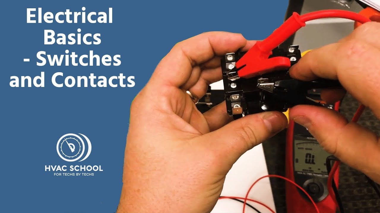
Electrical Basics – Switches and Contacts by HVAC School provides general background. The exact switch and equipment still require their own documentation and validation.
Frequently asked questions
이 토글 스위치 사진으로 단자 위치를 확인할 수 있나요?
아니요. 사진으로는 패키지와 단자 수는 보여줄 수 있지만, 내부 접점 구성, 뷰 방향, 램프 회로 또는 정격을 안정적으로 확인할 수 없습니다. 정확한 모델 도면과 개별 테스트를 사용하세요.
인쇄된 암페어 값이 모든 부하에 적용되나요?
아니오. 허용되는 값은 전압, AC 또는 DC, 부하 범주, 돌입 전류, 스위칭 주파수, 온도 및 제조업체 테스트 조건에 따라 다릅니다. 실제 애플리케이션에 명시된 정격 중에서 선택하십시오.
연속성 테스터를 사용하여 접점을 확인할 수 있습니까?
예, 모든 전원이 차단되고 저장된 에너지가 방전된 상태에서 가능합니다. 모든 위치를 테스트하고, 램프 회로가 저항 값을 발생시킬 수 있음을 인지하며, 매트릭스를 제조사 문서와 비교하십시오.
스위치가 모터나 솔레노이드 전류를 직접 흘려야 합니까?
정확한 부하와 사용률이 문서화된 정격 내에 있는 경우에만 해당됩니다. 돌입 전류가 더 크거나, 빈번하게 작동하거나, 위험에 민감한 기계의 경우, 적절하게 선택된 릴레이나 접촉기가 더 나은 인터페이스인 경우가 많습니다.
최종 배선 기록에는 어떤 정보가 들어가야 합니까?
주문 코드, 단자대 보기 방향, 접점 매트릭스, 도체 식별자, 보호 장치, 전원, 부하, 라벨, 시험 결과, 문서 개정판 및 승인일을 기록하십시오.
Final verification rule
Approve the installation only when the exact device identity, contact matrix, lamp behavior, mechanical fit, environmental boundary, load rating, protective measures, labels and test results all agree. Resolve every discrepancy before energizing production equipment. Keep the final record with the machine so a later replacement is checked against evidence rather than appearance.



